Supercharge Your Innovation With Domain-Expert AI Agents!

Variable capacitor and electronic device

A technology for electronic devices and capacitors, which can be applied to capacitors with variable voltage, single resonant circuits with only variable inductance/capacitance, and structural connection of antenna grounding switches, which can solve problems such as deterioration of Q-value characteristics.

Inactive Publication Date: 2018-01-09
TAIYO YUDEN KK
View PDF10 Cites 0 Cited by
  • Summary
  • Abstract
  • Description
  • Claims
  • Application Information

AI Technical Summary

Problems solved by technology

However, when the response is made faster, the characteristics including the Q value etc. deteriorate

Method used


Image

  • Variable capacitor and electronic device
  • Variable capacitor and electronic device
  • Variable capacitor and electronic device

Examples


no. 1 approach

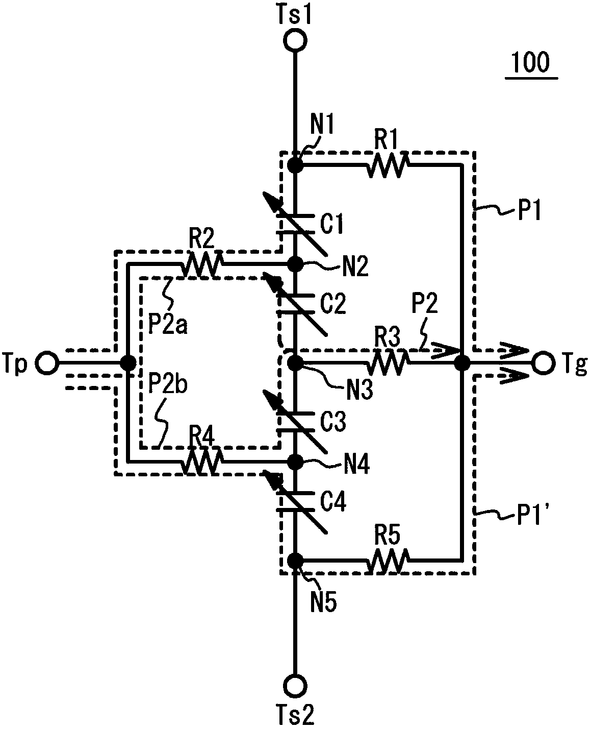
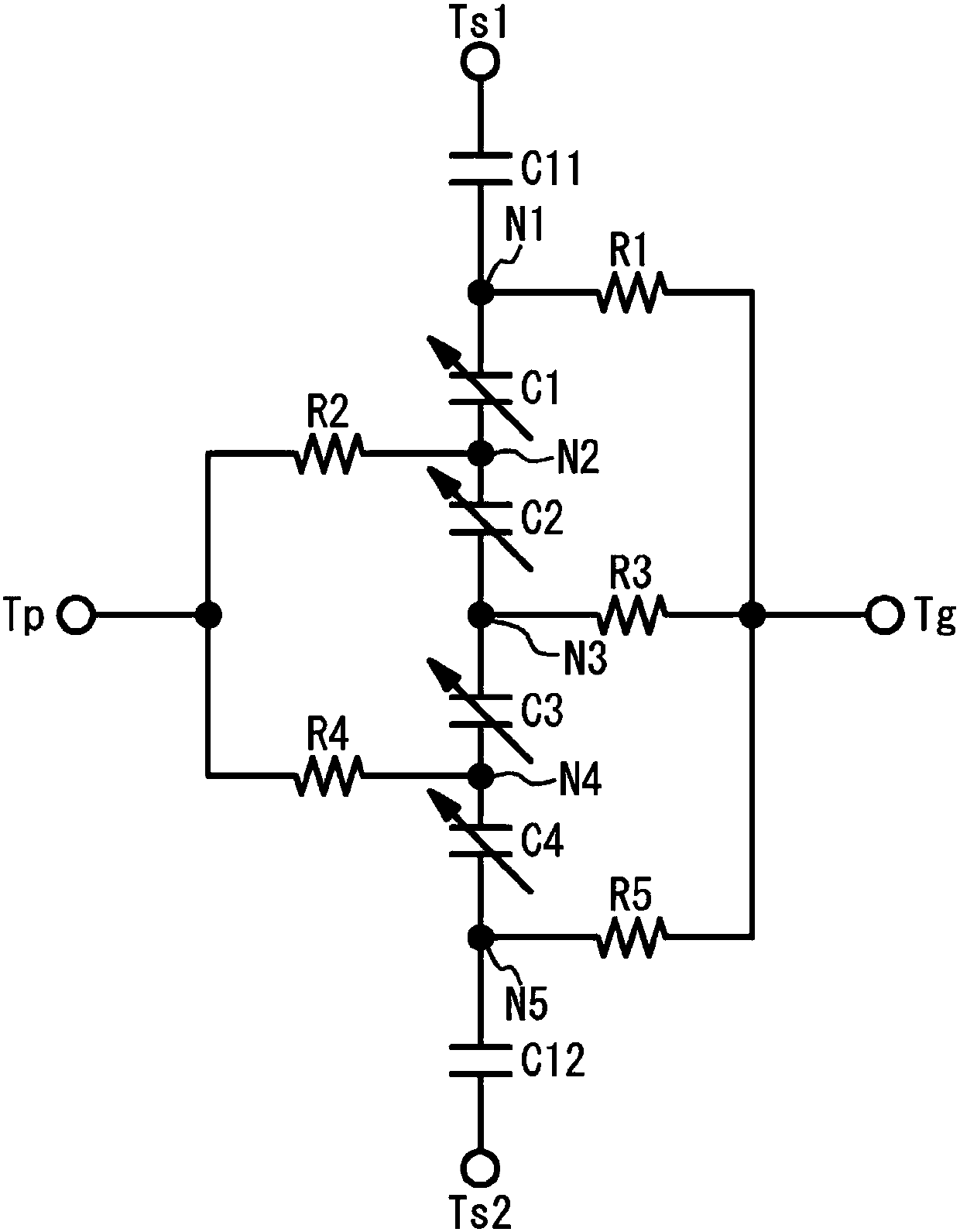
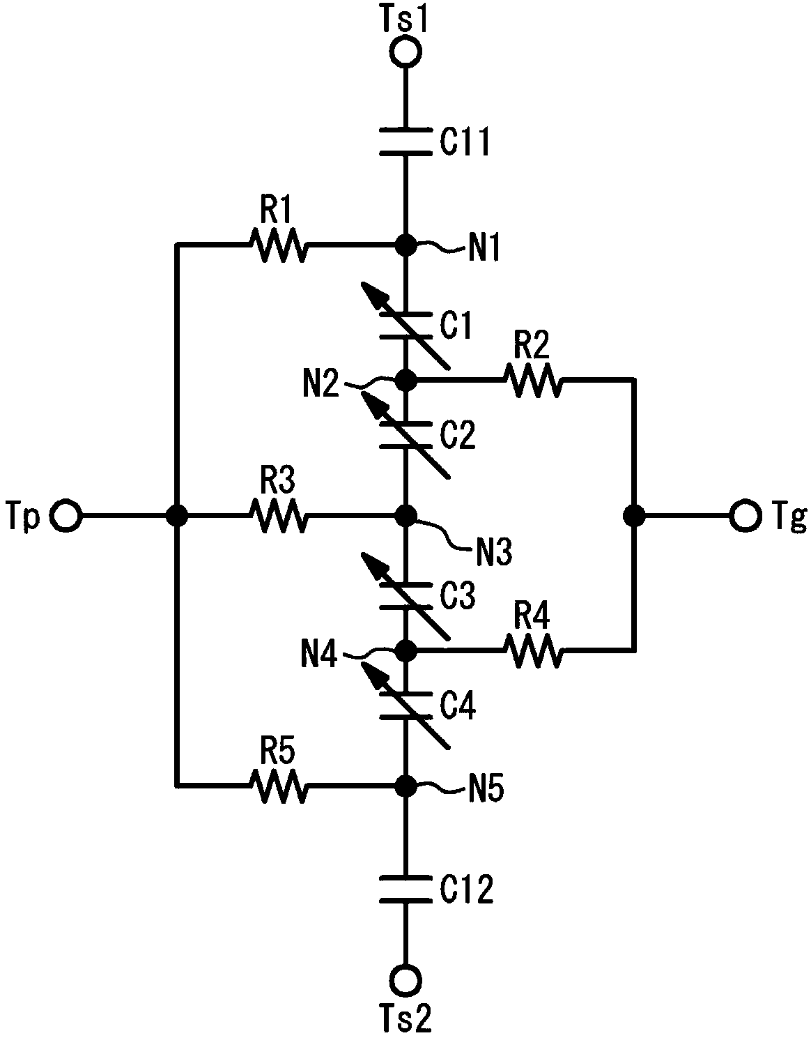
[0025] figure 1 is a circuit diagram of the variable capacitor 100 used to execute the simulation 1 in the first embodiment. Such as figure 1 As shown, the capacitors C1 to C4 are connected in series between the signal terminals Ts1 and Ts2. The resistor R1 is connected between the node N1 of the capacitor C1 that is closer to the signal terminal Ts1 and the fixed terminal Tg. The resistor R2 is connected between the node N2 located between the capacitors C1 and C2 and the variable terminal Tp. The resistor R3 is connected between the node N3 located between the capacitors C2 and C3 and the fixed terminal Tg. The resistor R4 is connected between the node N4 located between the capacitors C3 and C4 and the variable terminal Tp. The resistor R5 is connected between the node N5 of the capacitor C4 which is closer to the signal terminal Ts2 and the fixed terminal Tg.

[0026] For example, an AC signal of 13.56 MHz is input to the signal terminals Ts1 and Ts2. A variable volt...

no. 2 approach

[0092] Figure 15 An electronic device according to a second embodiment is shown. Such as Figure 15 As shown, the electronic device is an antenna circuit 106 operating unbalanced. The antenna circuit 106 includes a circuit 90, an antenna coil 92 connected in parallel with the circuit 90, a variable capacitor 94, and a capacitor 96 for removing direct current. The circuit 90 processes received signals received by means of the antenna coil 92 . Circuit 90 controls the supply of DC bias voltage to variable capacitor 94 . The variable capacitor 94 may be the variable capacitor described in the first embodiment and its modifications.


PUM


Abstract

A variable capacitor includes: capacitors connected in series between first and second signal terminals, capacitances of the capacitors varying in accordance with variable voltage applied to a variable terminal; a first resistor connected between a first node between adjacent capacitors of the capacitors and the variable terminal, a second resistor connected between a second node between adjacentcapacitors of the capacitors and a fixed terminal applied with fixed voltage, and a third resistor connected between a third node and the fixed terminal, the third node being located between the firstand / or second signal terminal and a capacitor located closest to the first and / or signal terminal among the capacitors, wherein a resistance of the second resistor is less than 1 and 1 2 or greaterwith respect to a resistance of the third resistor, and the resistance of the second resistor is not equal to a resistance of the first resistor.

Description

technical field [0001] Certain aspects of the invention relate to variable capacitors and electronic devices. Background technique [0002] In, for example, a near field communication (NFC) module and a wireless power transmission module, variability in electrical characteristics of a coil for an antenna and a usage environment cause a predetermined resonance frequency to change. As the size of mobile terminals has decreased in recent years, the size of antennas has also decreased. Therefore, the change of the resonant frequency becomes unacceptable in the circuit design. Thus, in order to adjust the resonance frequency, it is known to use a variable capacitor whose capacitance changes according to a DC bias voltage as disclosed in, for example, Japanese Patent Application Publication No. 2010-55570. [0003] There are also known variable capacitors as disclosed in, for example, Japanese Patent Application Publications No. 2010-55570, No. 2011-119482, No. 2008-66682, No. 2...

Claims


Application Information

Patent Timeline
Patent Type & Authority Applications(China)
IPC IPC(8): H01G7/06
CPCH03J3/20H01Q1/50
Inventor 夏目真志池永伦和
Owner TAIYO YUDEN KK
Features
  • R&D
  • Intellectual Property
  • Life Sciences
  • Materials
  • Tech Scout
  • Unparalleled Data Quality
  • Higher Quality Content
  • 60% Fewer Hallucinations
Learn More