

Electric connector
A technology of electrical connectors and contact parts, applied in the direction of conductive connection, connection, welding/welding connection, etc., can solve problems such as insufficient heating, virtual welding, unstable welding, etc., and achieve good welding effect, full utilization, and easy assembly The effect of entering the storage tank
- Summary
- Abstract
- Description
- Claims
- Application Information
AI Technical Summary
Problems solved by technology
Method used
Image

Examples
Embodiment Construction
[0032] In order to facilitate a better understanding of the purpose, structure, features, and effects of the present invention, the present invention will now be further described in conjunction with the accompanying drawings and specific embodiments.
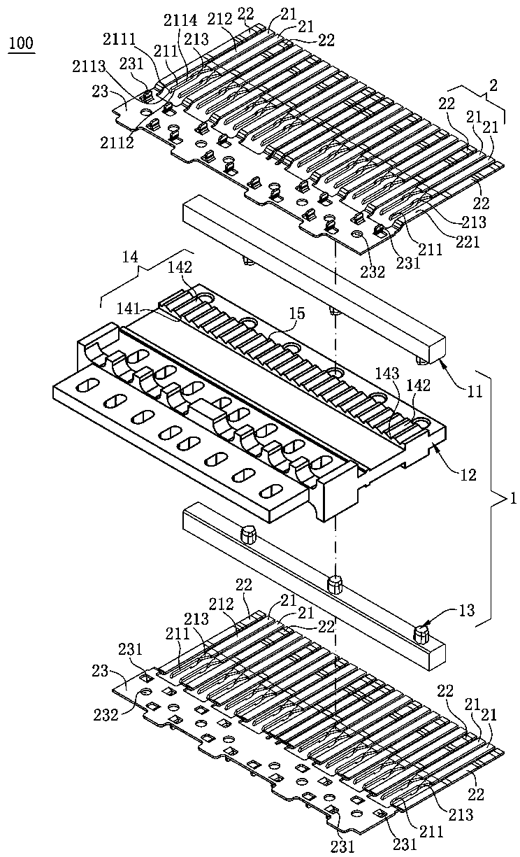
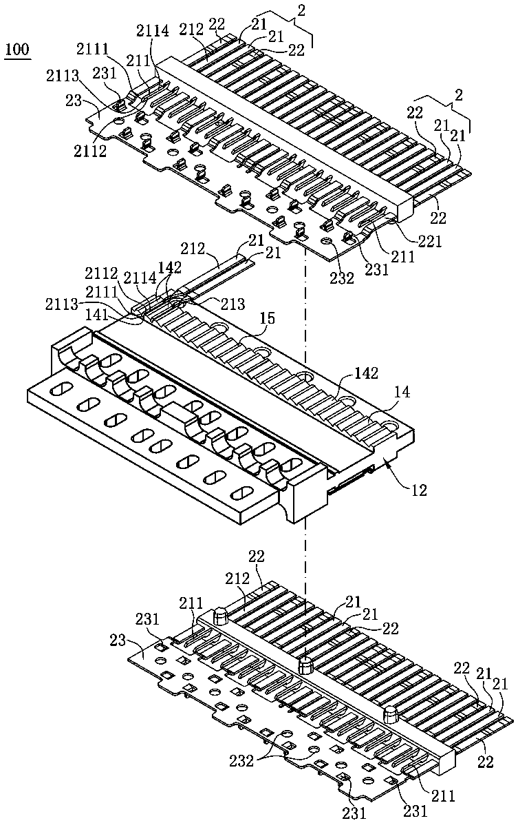
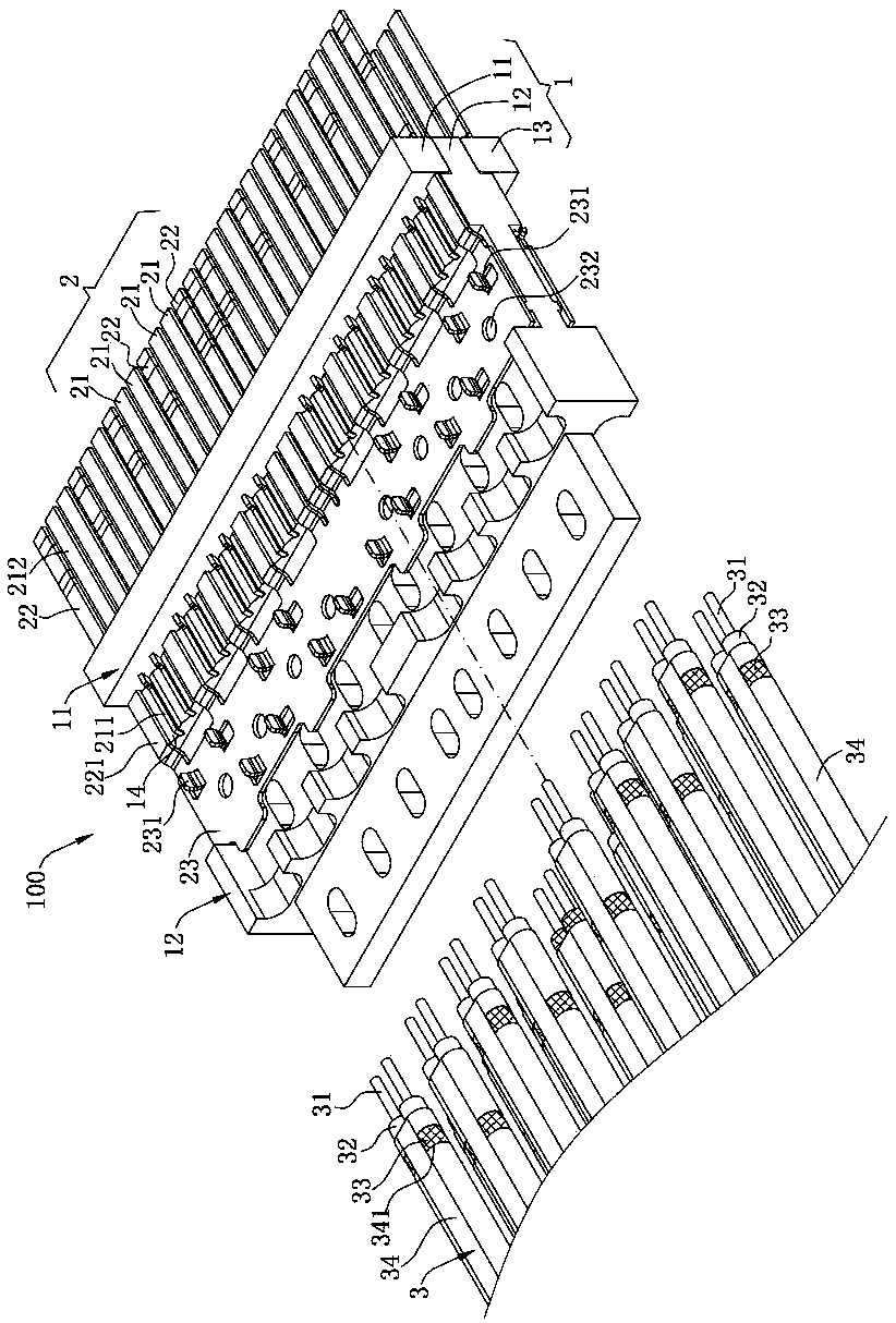
[0033] Such as figure 1 and image 3 As shown, the electrical connector 100 of the present invention includes an insulating body 1 and a plurality of terminals 2 for connecting with a plurality of cables 3 .
[0034] Such as figure 1 and Figure 6 As shown, the insulating body 1 is assembled from an upper body 11, a middle body 12 and a lower body 13. The rear ends of the three are flush, and the middle body 12 extends forward beyond the upper body 11 and the lower body 13. The middle body 12 The upper surface and the lower surface of the upper and lower surfaces are respectively provided with a plurality of receiving grooves 14, which are arranged in two rows up and down and run through the middle body 12 along the front an...
PUM
 Abstract
Description
Claims
Application Information