Heat dissipation device for motor

A heat dissipation device and motor technology, applied in electromechanical devices, casings/covers/supports, electrical components, etc., can solve problems such as motor damage, high risk, and automation equipment damage

Inactive Publication Date: 2018-01-09
SUZHOU FORCECON ELECTRIC
View PDF4 Cites 0 Cited by
  • Summary
  • Abstract
  • Description
  • Claims
  • Application Information

AI Technical Summary

Problems solved by technology

Since many automatic machines work for a very long time, the driving motor will inevitably generate a lot of heat during the long working process. As the heat continues to rise, if it is not properly cooled, it will easily cause motor damage. damage, which in turn may cause damage to automation equipment, which is extremely risky

Method used


Image

  • Heat dissipation device for motor
  • Heat dissipation device for motor

Examples


Embodiment 1

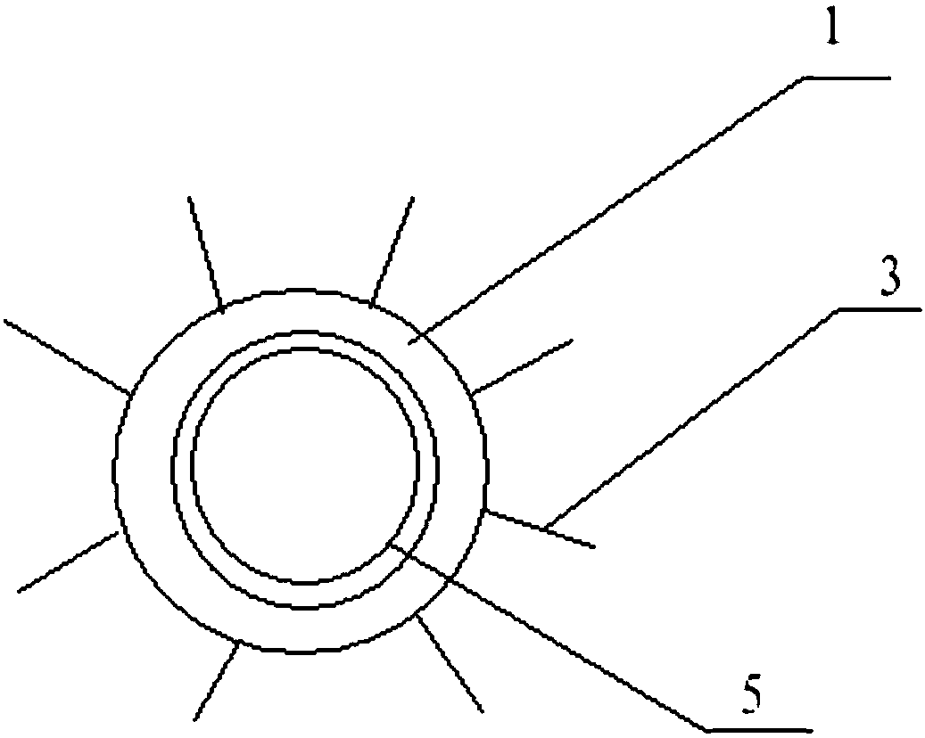
[0022] Such as Figure 1-2 As shown, a heat dissipation device for a motor includes a shell assembly and a heat conduction sheet;

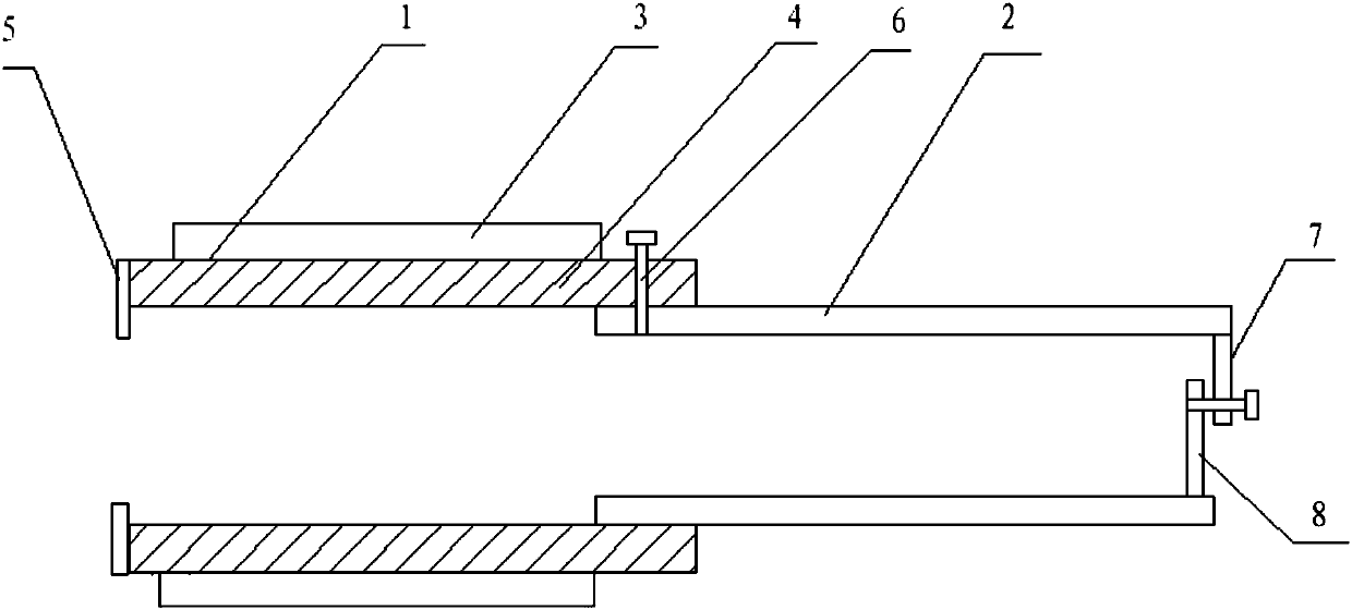
[0023] The housing assembly includes a coaxial first housing 1 and a second housing 2, both of which are open at the top and bottom; the first housing 1 is a cavity structure, including an inner wall and a The outer wall in contact with the outside world is provided with several cooling fins 3 extending along its axial direction, and each cooling fin 3 is arranged at equal intervals; preferably, the cooling fins 3 are in the shape of a wide middle and small ends. , which can facilitate the dissipation of heat outward;

[0024] The length of the second housing 2 is less than the length of the first housing 1, which is a single-layer structure, and its outer wall is attached to the inner wall of the first housing 1, and can slide along the inner wall of the first housing 1, Its inner diameter matches the outer diameter of the motor to be dissipate...

Embodiment 2

[0032] Based on Embodiment 1, in this embodiment, in order to improve the heat dissipation performance of the heat sink, the end of the first housing 1 away from the second housing is provided with a baffle 5, and the baffle 5 is along the first The radial extension of the shell 1 partially covers the opening at the end of the first shell 1; the first shell 1 is also provided with a positioning pin 6, and the positioning pin 6 is arranged perpendicular to the first shell 1, And penetrate through the outer wall and inner wall of the first housing 1 to limit the movement of the second housing 2 .

[0033] Further, symmetrically arranged first rotating pieces 7 and second rotating pieces 8 are hinged on the edge of the end of the second casing 2 away from the first casing, and the first rotating pieces 7 and the second rotating pieces 8 connected by screws,

[0034] In actual use, first attach one end of the motor to be dissipated to the baffle, and then adjust the position of t...


PUM


Abstract

The invention discloses a heat dissipation device for a motor. The heat dissipation device comprises a shell assembly and a heat conduction piece. The shell assembly comprises a first shell and a second shell which are coaxially arranged. The tops and the bottoms of the two shells are in the opened state. The first shell is of a cavity structure and comprises an inner wall and an outer wall in contact with the outside. A plurality of radiating fins, which are extending along the axial direction, are arranged on the outer wall. The radiating fins are arranged at equal intervals. The length of the second shell is smaller than the length of the first shell. The second shell is of a single-layer structure. The outer wall of the second shell is attached to the inner wall of the first shell. Thesecond shell can slide along the inner wall of the first shell. The inner diameter of the second shell is matched with the outer diameter of a to-be-cooled motor. The heat conduction piece is arranged in the cavity of the first shell to fully fill the cavity of the first shell. The device is simple in structure and good in heat dissipation effect. The continuous operation of automatic products can be effectively guaranteed, and the production is not influenced by any factor at all.

Description

technical field [0001] In particular, the invention relates to a heat dissipation device for a motor. Background technique [0002] With the continuous development of automation technology, more and more automation products will use motors to realize the drive. The working principle is to drive the starter rotor to rotate through electromagnetic induction, and the small gear on the rotor drives the engine flywheel to rotate. Since many automatic machines work for a very long time, the driving motor will inevitably generate a lot of heat during the long working process. As the heat continues to rise, if it is not properly cooled, it will easily cause motor damage. damage, which may cause damage to automation equipment, which is extremely risky. Contents of the invention [0003] In view of the above problems, the present invention proposes a heat dissipation device for motors, which has a simple structure and good heat dissipation effect, and can effectively ensure continu...

Claims


Application Information

Patent Timeline
Patent Type & Authority Applications(China)
IPC IPC(8): H02K5/18H02K5/04
Inventor 饶振奇赖俊男
Owner SUZHOU FORCECON ELECTRIC
Why Eureka
Try Eureka