Glue filling device of permanent-magnet synchronous-motor rotor assembly and flue filling method of glue filling device

A permanent magnet synchronous motor and glue filling technology, which is applied to the surface coating liquid device, manufacturing stator/rotor body, coating, etc., can solve the problems of capacity limitation, work surface cleaning, glue overflow and other problems, and achieve operation Convenience, improved perfusion efficiency, and improved accuracy

Pending Publication Date: 2018-01-09
NANJING YUEBO ELECTRIC DRIVE SYST CO LTD
View PDF1 Cites 7 Cited by
  • Summary
  • Abstract
  • Description
  • Claims
  • Application Information

AI Technical Summary

Problems solved by technology

[0003] However, the above-mentioned fixing method has the following technical problems: 1. A small amount of air bubbles are wrapped by the glue during the potting process, and remain in the glue after curing, which affects the bonding strength between the magnetic steel and the notch; 2. During manual filling, The control of the amount of glue used is not accurate, and there will be more scraping and less replenishment in the later stage; 3. Glue overflow caused by manual potting, cleaning of the work surface and the environment; 4. The production efficiency of manual potting is low, and the production capacity is severely limited

Method used


Image

  • Glue filling device of permanent-magnet synchronous-motor rotor assembly and flue filling method of glue filling device
  • Glue filling device of permanent-magnet synchronous-motor rotor assembly and flue filling method of glue filling device
  • Glue filling device of permanent-magnet synchronous-motor rotor assembly and flue filling method of glue filling device

Examples


Embodiment Construction

[0029] The specific embodiments of the present invention will be described in further detail below in conjunction with the accompanying drawings.

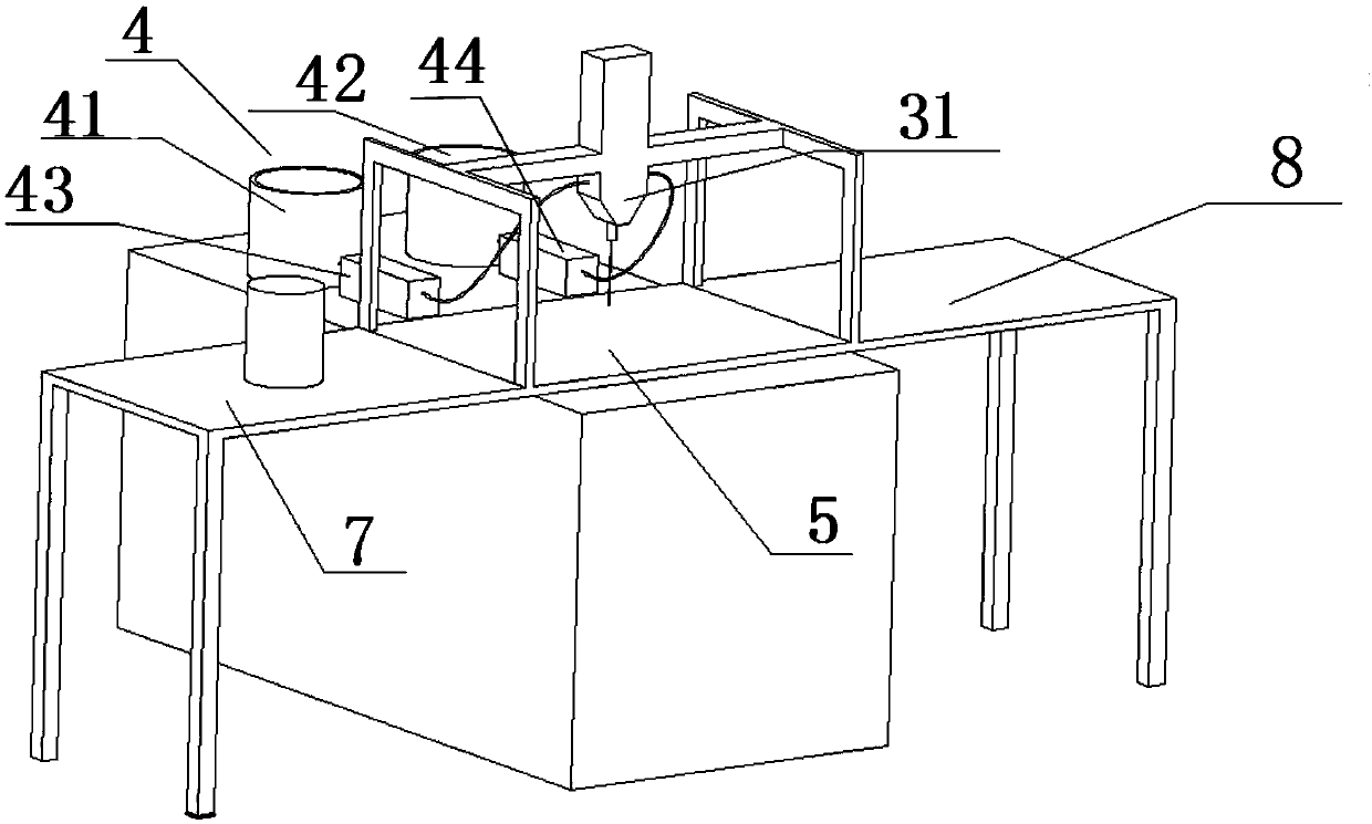
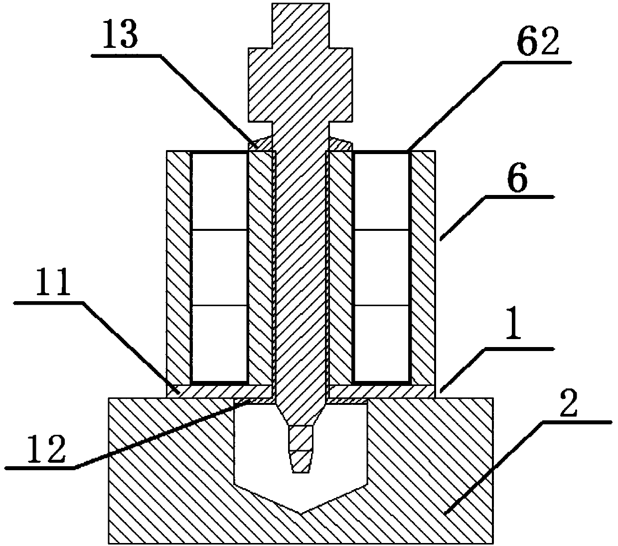
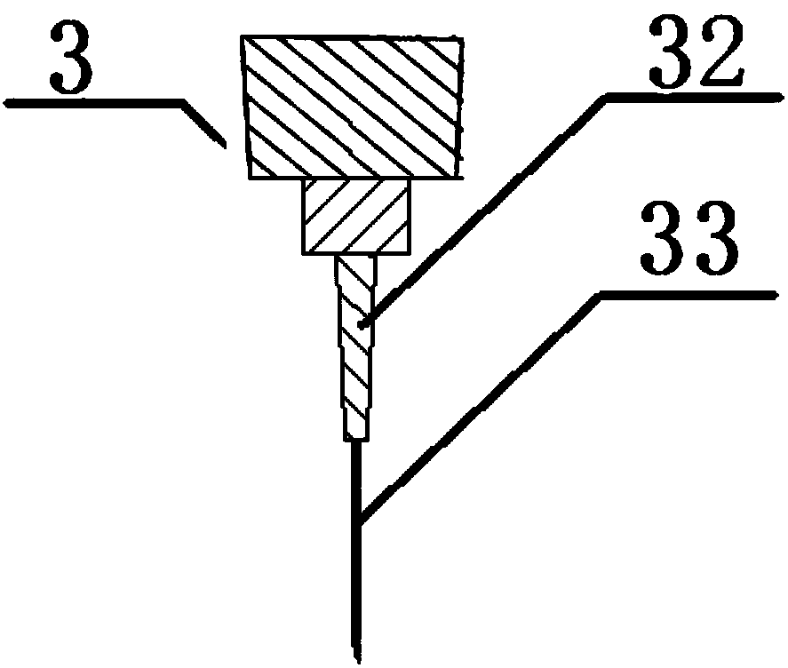
[0030] as attached Figure 1-3 As shown, a glue filling device for a rotor assembly of a permanent magnet synchronous motor includes a rotor assembly fixing device 1, a positioning fixture 2, a glue filling device 3, a glue storage device 4 and a glue filling device stand 5, and the rotor assembly 6 can be disassembled fixed on the rotor assembly fixing device 1, the rotor assembly fixing device 1 is detachably fixed on the positioning jig 2, and the positioning jig 2 is detachably fixed on the glue filling device On the stand 5, the glue storage device 4 is detachably fixed on the stand 5 of the glue filling device, the glue storage device 4 is connected to the glue filling device 3 and can deliver glue to the glue filling device 3 The glue filling device 3 is movable and fixedly arranged on the glue filling device stand 5, and t...


PUM


Abstract

The invention discloses a glue filling device for a rotor assembly of a permanent magnet synchronous motor and a glue filling method thereof. The glue filling device includes a rotor assembly fixing device, a positioning jig, a glue filling device, a glue storage device, and a glue filling device stand; The glue pouring method includes the following steps: Step 1: Adjust the position of the positioning jig; Step 2: Fix the front plate on the positioning jig; Step 3: Fix the rotor assembly on the front end plate and the rotor bracket through the positioning tool; Step 4: Start the three-axis manipulator; Step 5: According to the relative position of the glue filling point on the magnetic steel notch on the rotor assembly and the positioning point; Step 6: Drive the first delivery pump and the second delivery pump to pour the glue into the glue Fill the mixing tube and injection needle. The glue pouring device of the present invention can effectively improve the precision of glue pouring, and can effectively improve the pouring efficiency; the glue pouring method is easy to operate.

Description

technical field [0001] The invention relates to the technical field of glue filling for motor rotor components, in particular to a glue filling device and a glue filling method for a rotor component of a permanent magnet synchronous motor. Background technique [0002] At present, the assembly method of the permanent magnet magnet in the rotor assembly of the permanent magnet synchronous motor is: reserve a slot on the rotor punch, and when the punch is stacked into an iron core, a magnet groove for assembling the magnet is formed; in order to reduce the assembly Difficulty, the gap between the magnet and the notch is matched, and glue is used to fix it during assembly to prevent the magnet from vibrating in the slot when the motor is running. The glue used can be epoxy AB glue, anaerobic glue, etc., and the filling method is mostly manual. Glue manually. [0003] However, the above-mentioned fixing method has the following technical problems: 1. A small amount of air bubbl...

Claims


Application Information

Patent Timeline
Patent Type & Authority Applications(China)
IPC IPC(8): H02K15/03B05C5/02B05C13/02B05C11/10B05C11/11
Inventor 李占江高超蒋元广李艳会包玉衡
Owner NANJING YUEBO ELECTRIC DRIVE SYST CO LTD
Why Eureka
Try Eureka