Supercharge Your Innovation With Domain-Expert AI Agents!

Grinding roller with a cooling device

A technology of cooling device and grinding roller, applied in the field of grinding roller, can solve the problems of expensive installation space and assembly, difficulty in manufacturing and high production cost, and achieve the effect of saving cost and time, saving cost and reducing parts.

Inactive Publication Date: 2018-01-09
THYSSENKRUPP IND SOLUTIONS AG +1
View PDF7 Cites 0 Cited by
  • Summary
  • Abstract
  • Description
  • Claims
  • Application Information

AI Technical Summary

Problems solved by technology

This known cooling device for grinding rollers is difficult to manufacture and expensive to produce, and in addition, assembly, especially in a working environment with a small installation space, is expensive

Method used


Image

  • Grinding roller with a cooling device
  • Grinding roller with a cooling device

Examples


Embodiment Construction

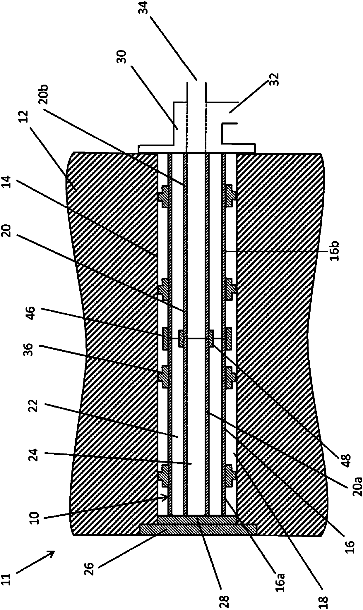
[0026] figure 1 A section is shown of a grinding roller shaft 12 on which grinding rollers are mounted in a manner not shown. Roller shaft 12 includes an axial bore 14 extending through roll shaft 12 . Furthermore, the grinding roller shaft 12 includes a cooling device 10 arranged in a bore 14 . The cooling device 10 comprises a first tube 16 arranged in and coaxially with the bore 14 . The outer diameter of the first tube 16 is smaller than the inner diameter of the hole 14 , so that a first conduit 18 for guiding the coolant is formed between the inner surface of the hole 14 and the outer surface of the tube 16 . A second tube 20 is arranged coaxially with the first tube. The second tube 20 has a smaller diameter than the first tube 16 and is arranged within the first tube 16 such that a gap 22 is formed between the first tube 16 and the second tube 20 . A second pipe 24 for guiding coolant is formed inside the second pipe 20 . The first tube 16 and the second tube 20 a...


PUM


Abstract

The present invention relates to a grinding roller (11) for a rolling mill, which grinding roller is mounted on a grinding roller shaft (12) so as to be rotatable about its longitudinal axis, whereinthe grinding roller shaft (2) has an axial bore (14) in which there is arranged a cooling device (10) which has at least one pipe (16, 20) which is arranged in the bore (14), wherein a first duct (18)for guiding a coolant is formed between the pipe (16, 20) and the inner surface of the bore (14) and a second duct (24) for guiding the coolant is formed within the pipe (16, 20), wherein the at least one pipe (16, 20) is formed from a plastic.

Description

technical field [0001] The invention relates to a grinding roller for a roller mill, which has a cooling device for cooling the grinding roller. Background technique [0002] Grinding rollers are commonly used for crushing materials such as rocks, ores, coal and other raw materials. The known grinding rolls comprise two roll bodies which rotate counter to each other and grind the material located between the grinding rolls. [0003] Heat is generated during the grinding process, in particular at the bearing points of the shafts and on the roller surfaces, which leads to an increase in the temperature of the grinding system and thus requires cooling. Typically, the grinding roller shaft is cooled by a cooling water circuit in the shaft bore, whereby coolant is guided through the bore in the grinding roller shaft. During the operation of known cooling devices, damage often occurs due to deposits and corrosion at the grinding roller shaft and at the cooling device. [0004] ...

Claims


Application Information

Patent Timeline
IPC IPC(8): B02C4/44
CPCB02C4/44
Inventor 克里斯蒂娜·西克曼安德烈·多恩布卢特卡斯滕·伯克
Owner THYSSENKRUPP IND SOLUTIONS AG
Features
  • R&D
  • Intellectual Property
  • Life Sciences
  • Materials
  • Tech Scout
  • Unparalleled Data Quality
  • Higher Quality Content
  • 60% Fewer Hallucinations
Learn More