Chemical raw material stirring device

A stirring device and technology for chemical raw materials, applied in the direction of mixer accessories, chemical instruments and methods, dissolution, etc., can solve the problems of poor stirring effect, inability to stir the top layer of material and the bottom layer of material, etc., to achieve convenient operation and good supporting effect , Guarantee the effect of quality

Inactive Publication Date: 2018-01-12
COMMON TECH DEV CO LTD
View PDF3 Cites 2 Cited by
  • Summary
  • Abstract
  • Description
  • Claims
  • Application Information

AI Technical Summary

Problems solved by technology

[0003] A mixer is a mechanical device that evenly mixes materials. In many cases, the stirring shaft of the mixer is set vertic

Method used


Image

  • Chemical raw material stirring device
  • Chemical raw material stirring device
  • Chemical raw material stirring device

Examples


Embodiment 1

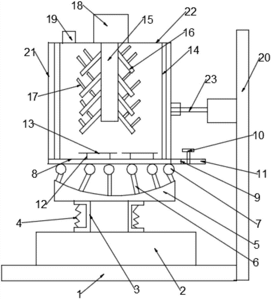
[0020] A stirring device for chemical raw materials, comprising a base 1, a stirring body 21 and a stirring device, the upper end of the base 1 is provided with a first fixed block 2, and buffer plates 3 are installed on both sides of the upper end of the first fixed block 2, and the buffer plate 3 The shape is inverted U-shaped and each buffer plate 3 is provided with a buffer spring 4, a second fixed block 5 is installed on the upper end of the buffer plate 3, a roller 7 is installed on the second fixed block 5, and the bottom of the stirring body 21 is in contact with the roller 7. contact, the upper end of the stirring body 21 is provided with a feed inlet 19 and a stirring motor 18, one side of the stirring body 21 bottom is provided with a discharge pipe 11, and a stirring device is arranged in the stirring body 21, and the stirring device includes a stirring shaft 15, a stirring wheel 16 and stirring member 17, stirring shaft 15 is connected with the output end of stirri...

Embodiment 2

[0022] A stirring device for chemical raw materials, comprising a base 1, a stirring body 21 and a stirring device, the upper end of the base 1 is provided with a first fixed block 2, and buffer plates 3 are installed on both sides of the upper end of the first fixed block 2, and the buffer plate 3 The shape is inverted U-shaped and each buffer plate 3 is provided with a buffer spring 4, the upper end of the buffer plate 3 is equipped with a second fixed block 5, the second fixed block 5 is equipped with a roller 7 through a fixed column 6, and the bottom of the stirring body 21 In contact with the roller 7, the upper end of the stirring body 21 is provided with a feed inlet 19 and a stirring motor 18, one side of the bottom of the stirring body 21 is provided with a discharge pipe 11, and a stirring device is arranged in the stirring body 21, and the stirring device includes a stirring shaft 15. The stirring wheel 16 and the stirring member 17, the stirring shaft 15 is connect...


PUM


Abstract

The invention discloses a chemical raw material stirring device, which comprises a base, a stirring body and a stirring device, wherein a first fixing block is arranged at the upper end of the base, and a buffer plate is arranged at the upper end of the first fixing block; a buffer spring is arranged in the buffer plate, and a second fixing block is arranged at the upper end of the buffer plate; rollers are arranged on the second fixing block, and the bottom of the stirring body is in contact with the rollers; a stirring device is arranged in the stirring body, and the stirring device comprises a stirring shaft, stirring wheels and stirring components; a bottom plate is arranged in the stirring body, and horizontal blades are arranged on the bottom plate; a first bracket is arranged on thebase, and a swinging mechanism is arranged on the first bracket; the swinging mechanism is hinged with the stirring body. The device can realize full stirring and crushing of raw materials through the cooperation of a stirring motor, the stirring shaft, the stirring wheels, the stirring components, the horizontal blades and vertical blades so as to ensure the quality of stirring; the swinging mechanism drives the stirring body to reciprocate horizontally, thus strengthening the stirring and crushing effects.

Description

technical field [0001] The invention relates to a stirring device, in particular to a chemical raw material stirring device. Background technique [0002] The relationship between human beings and chemical industry is very close, and it has spread to all aspects of life. The chemical industry includes petrochemical, agricultural chemical, chemical medicine, polymer, paint, oil, etc. In modern life, chemical products are inseparable almost anytime and anywhere. From material life such as clothing, food, housing and transportation to spiritual life such as culture, art and entertainment, chemical products are required to serve them. Some chemical products play an epoch-making important role in the history of human development. The existing chemical raw materials need to be produced through chemical reactions in the production process, and in the process of chemical reactions, because the reactants cannot be fully contacted, the reactants cannot completely undergo chemical re...

Claims


Application Information

Patent Timeline
IPC IPC(8): B01F13/10B01F15/00B01F15/02
Inventor 周秋伟
Owner COMMON TECH DEV CO LTD
Why Eureka
Try Eureka