
Aluminum alloy die casting mold

A die-casting mold and aluminum alloy technology, which is applied in the field of aluminum alloy die-casting molds, can solve the problems of low production efficiency, difficult to achieve automatic spraying, and affect the safety of operators, so as to improve efficiency, improve cooling and demoulding effects, and improve quality. Effect

Active Publication Date: 2018-01-12
宁波环亚机械制造有限公司
View PDF12 Cites 9 Cited by
  • Summary
  • Abstract
  • Description
  • Claims
  • Application Information

AI Technical Summary

Problems solved by technology

[0006] The first purpose of the present invention is to provide an aluminum alloy die-casting mold that can easily form shrinkage depressions and shrinkage holes in thicker parts of the existing aluminum alloy die-casting molds Effectively improve shrinkage sag and shrinkage hole problems under the premise of design, thereby improving the strength and quality of die castings
[0007] The second purpose of the present invention is to solve the problems of difficulty in automatic spraying, low production efficiency, and affecting the safety of operators when spraying mold release agents in die-casting molds with horizontal core-pulling sliders, and to provide a The aluminum alloy die-casting mold can realize the automatic spraying of the die-casting release agent, and the spraying of the release agent is uniform, which is beneficial to the release of the horizontal core-pulling slider

Method used

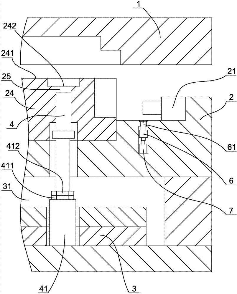

Image

  • Aluminum alloy die casting mold
  • Aluminum alloy die casting mold
  • Aluminum alloy die casting mold

Examples


Embodiment Construction

[0026] The present invention will be further described below in conjunction with the accompanying drawings and specific embodiments.

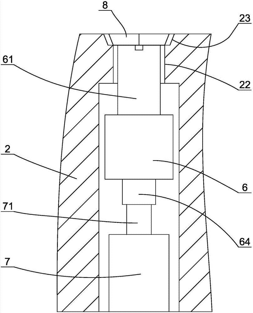
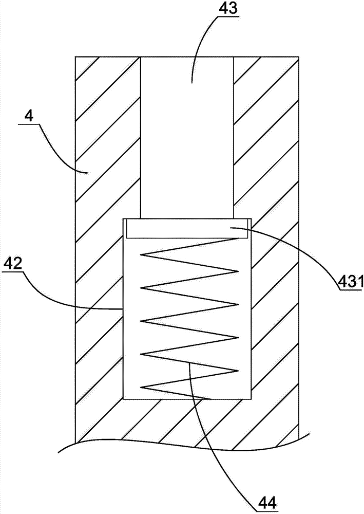
[0027] Such as figure 1 As shown, an aluminum alloy die-casting mold is suitable for forming aluminum alloy die-casting parts with sudden changes in wall thickness and deep lateral holes. Concretely comprise the upper mold 1 that is positioned at die-casting mold top and has mold cavity, the lower mold 2 that is positioned at die-casting mold bottom, the mold core 24 that is fixedly arranged on the lower mold, the transverse core-pulling slider 21 that is movably arranged on the lower mold and is positioned at The bottom of the lower mold has a top plate 3 of a push rod, and an ejection gap 31 is arranged between the top plate and the lower mold. There is a lateral hole forming part on the lower mold, and one end of the horizontal core-pulling slider is a forming end matched with the lateral hole forming part, so that the lateral hole groove c...


PUM


Abstract

The invention discloses an aluminum alloy die casting mold. The aluminum alloy die casting mold comprises an upper mold, a lower mold and an ejector plate; the lower mold is provided with a transversecore pulling slide block; a mold core outer molding surface of the lower mold consists of a first molding surface and a second molding surface; the wall thickness of a die-cast piece corresponding tothe second molding surface is larger than the wall thickness of a die-cast piece corresponding to the first molding surface; a mold core is provided with a feeding hole in the second molding surface;a pressing rod associated with a driving oil cylinder is arranged in the feeding hole; the driving oil cylinder enables the pressing rod to axially move from a molding position to a feeding position;the lower mold is provided with a spraying hole corresponding to the transverse core pulling slide block; a plunger spraying device is arranged in the spraying hole; a sealing plate associated with the plunger spraying device is arranged in an opening of the spraying hole; and the sealing plate has a molding state for shielding the plunger spraying device, and a spraying state for exposing the spraying hole outside. The aluminum alloy die casting mold can effectively improve the problems of shrinkage recesses and shrinkage holes, can realize automatic spraying of a die casting release agent,and facilitates demolding of the transverse core pulling slide block.

Description

technical field [0001] The invention relates to the technical field of aluminum alloy die-casting molds, in particular to an aluminum alloy die-casting mold that can effectively prevent shrinkage pores in die-casting parts and facilitate the demoulding of a horizontal core-pulling slider. Background technique [0002] Aluminum alloy die-casting molds usually include an upper mold, a lower mold, a cavity set on the upper mold to match the outside of the product, and a mold core set on the lower mold to match the inside of the product. During die-casting, the upper and lower molds are closed. At this time The gap between the inner molding surface of the cavity and the outer molding surface of the mold core is the molding cavity, and the high-temperature molten aluminum alloy liquid enters the molding cavity through the gate, and then is cooled by the cooling system to form an aluminum alloy The product is then ejected by the ejector mechanism. [0003] When the liquid aluminu...

Claims


Application Information

Patent Timeline
IPC IPC(8): B22D17/22B22D17/20
Inventor 朱立志
Owner 宁波环亚机械制造有限公司
Learn More