Supercharge Your Innovation With Domain-Expert AI Agents!

Novel ultrasonic wave belt cutting machine

A technology of ultrasonic and tape cutting machine, which is applied in metal processing, coiling strips, thin material processing, etc. It can solve the problems of occupying space, work efficiency and tape cutting style that cannot keep up with the progress and development of the times, and noise generation.

Active Publication Date: 2018-01-12
FUJIAN QIANGKUN MACHINERY EQUIP CO LTD
View PDF5 Cites 8 Cited by
  • Summary
  • Abstract
  • Description
  • Claims
  • Application Information

AI Technical Summary

Problems solved by technology

[0002] Most of the existing ultrasonic cutting machines are driven by air pressure, and the air pressure drives the user to increase equipment support, occupy space, and generate noise
The Chinese invention patent authorized by the applicant on July 10, 2013 with the name "An Ultrasonic Tape Cutting Machine" and the patent number ZL201110118439.0 uses a single motor to drive the synchronous movement of feeding and cutting, and realizes the method without air pressure. , but the work efficiency and cutting style cannot keep up with the progress and development of the times. At present, the cutting machine needs the characteristics of multi-function and high efficiency to adapt to the current market demand.

Method used


Image

  • Novel ultrasonic wave belt cutting machine
  • Novel ultrasonic wave belt cutting machine
  • Novel ultrasonic wave belt cutting machine

Examples


Embodiment 1

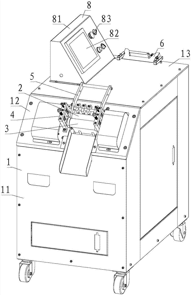
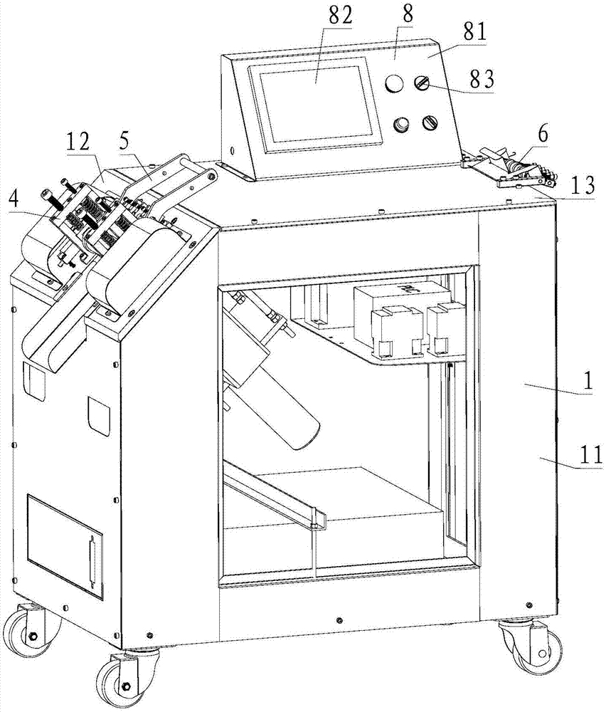
[0062] Please refer to Figure 1 to Figure 5 , Embodiment 1 of the present invention is:

[0063] A new type of ultrasonic cutting machine, including a frame 1, also includes a feeding mechanism 2 and a roll cutting mechanism 3, the frame 1 includes a main housing 11 and a first workbench 12, the first workbench 12 is fixed on The top of the main housing 11; the feeding mechanism 2 includes a feeding motor 21, a feeding roller 22 and a feeding roller 23, the feeding motor 21 drives the feeding roller 22 to rotate, and the feeding roller 23 is located on the feeding roller 23. Directly above the roller 22, the feeding roller 22 and the feeding pressure roller 23 are connected in rotation with the first workbench 12, and the feed motor 21 is fixed on the first workbench 12; Mechanism 3 comprises hobbing motor 31, hobbing cutter 32 and ultrasonic horn 33, and described hobbing motor 31 drives described hobbing cutter 32 to rotate, and described hobbing cutter 32 is cylindrical, ...

Embodiment 2

[0064] Please refer to Figure 1 to Figure 5 , the second embodiment of the present invention is:

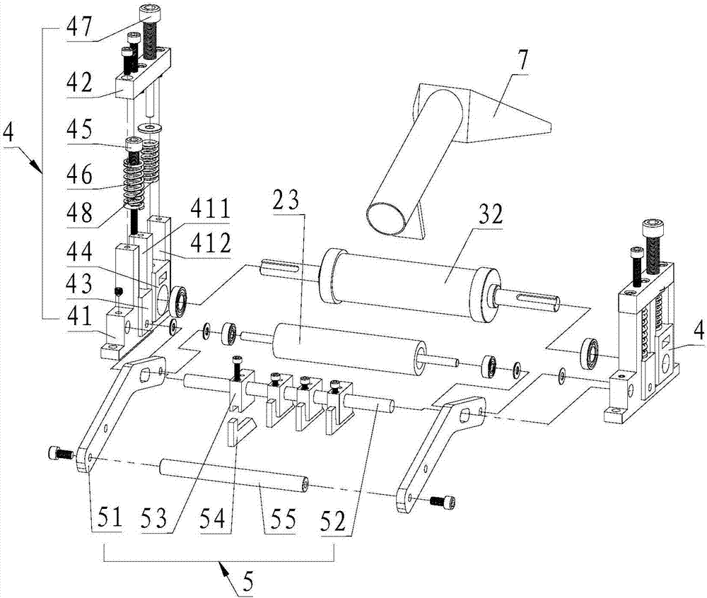
[0065]A new type of ultrasonic belt cutting machine, on the basis of the first embodiment, also includes a pre-tension mechanism 4, the pre-tension mechanism 4 includes a fixed seat 41, a pressure plate 42, a first slider 43, a second slider 44, a first A screw guide post 45, a first spring 46, a second screw guide post 47 and a second spring 48, the pressing plate 42 is fixed on the top surface of the fixed seat 41, and the upper surface of the fixed seat 41 is provided with a first recess groove 411 and a second groove 412, the first slider 43 is slid up and down in the first groove 411, and the second slider 44 is slid up and down in the second groove 412, so The upper end of the first screw guide post 45 is screwed to the pressure plate 42, and the lower end is slidably connected to the first slider 43. The first spring 46 is sleeved on the first screw guide post 45, and is...

Embodiment 3

[0066] Please refer to Figure 1 to Figure 5 , Embodiment three of the present invention is:

[0067] A new type of ultrasonic tape cutting machine, on the basis of the first or second embodiment, the feeding mechanism 2 also includes a first bevel gear set 24 and a first bearing seat 25, and the feeding motor 21 passes through the first bevel gear Group 24 is connected with described feeding roller 22, and the two ends of described feeding roller 22 are respectively connected with described first workbench 12 through a described first bearing seat 25; 34. The ultrasonic transducer 35, the first fan and the second fan, the ultrasonic generator 34, the ultrasonic transducer 35, and the ultrasonic welding head 33 are connected sequentially from bottom to top, and the air outlet of the first fan faces the The ultrasonic welding head 33, the air outlet of the second fan faces the ultrasonic transducer 35.


PUM


Abstract

The invention provides a novel ultrasonic wave belt cutting machine which comprises a rack and further comprises a material feeding mechanism and a rolling-cutting mechanism. The rack comprises a mainshell body and a first workbench, and the first workbench is fixedly arranged on the top of the main shell body; the material feeding mechanism comprises a material feeding motor, a material feedingroller and a material-feeding pressing roller, the material feeding roller is driven to rotate by the material feeding motor, the material-feeding pressing roller is located right above the material feeding roller, the material feeding roller and the material-feeding pressing roller are both rotatably connected with the first workbench, and the material feeding motor is fixedly arranged on the first workbench; the rolling-cutting mechanism comprises a rolling-cutting motor, a rolling-cutting cutter and an ultrasonic wave welding head, the rolling-cutting cutter is driven to rotate by the rolling-cutting motor and is of a cylinder shape, the outer circular surface of the rolling-cutting cutter is provided with cutting stripes in an integrated and protruding manner, the rolling-cutting cutter is located right above the ultrasonic wave welding head, arranged parallel to the material-feeding pressing roller and is rotatably connected with the first workbench, and the rolling-cutting motorand the ultrasonic wave welding head are fixedly arranged on the first workbench. Patterns of cut belts machined by the novel ultrasonic wave belt cutting machine can be more flexible.

Description

technical field [0001] The invention relates to the technical field of tape cutting machines, in particular to a novel ultrasonic tape cutting machine. Background technique [0002] Most of the existing ultrasonic tape cutting machines are driven by air pressure, and the air pressure drive increases equipment matching for users, occupies space and generates noise. The Chinese invention patent authorized by the applicant on July 10, 2013 with the name "An Ultrasonic Tape Cutting Machine" and the patent number ZL201110118439.0 uses a single motor to drive the synchronous movement of feeding and cutting, and realizes the method without air pressure. , but the work efficiency and tape cutting style can not keep up with the progress and development of the times. At present, the tape cutting machine needs the characteristics of multi-function and high efficiency to meet the current market demand. Contents of the invention [0003] The technical problem to be solved by the prese...

Claims


Application Information

Patent Timeline
IPC IPC(8): B26D1/25B26D1/00B26D7/08B65H20/02B65H23/26
Inventor 林志强林志坚王晓美
Owner FUJIAN QIANGKUN MACHINERY EQUIP CO LTD
Features
  • R&D
  • Intellectual Property
  • Life Sciences
  • Materials
  • Tech Scout
  • Unparalleled Data Quality
  • Higher Quality Content
  • 60% Fewer Hallucinations
Learn More