
Novel printing roller technology

A printing roller and technology, applied in the field of new printing rollers, can solve the problems of low treatment efficiency and large influence of treatment equipment, and achieve the effects of improving treatment efficiency, easy sewage treatment, and reducing bad influences

Inactive Publication Date: 2018-01-12
天津圣文纸制品股份有限公司
View PDF1 Cites 0 Cited by
  • Summary
  • Abstract
  • Description
  • Claims
  • Application Information

AI Technical Summary

Problems solved by technology

[0005] In order to solve the above technical problems, the present invention provides a new type of printing roller technology to solve the problems of low processing efficiency and great impact on processing equipment in the existing environmental protection zero discharge treatment system for sewage in printing workshops

Method used


Image

  • Novel printing roller technology

Examples


Embodiment

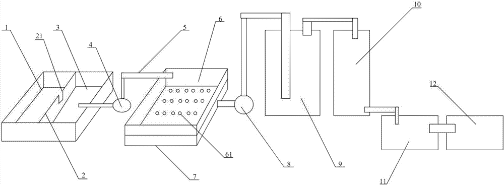
[0020] as attached figure 1 shown

[0021] The present invention provides a new type of printing roller technology, including a first sedimentation tank 1, an isolation dam 2, a second sedimentation tank 3, a first electric pump 4, a pipeline 5, a filter tank 6, a third sedimentation tank 7, and a second electric pump 8. Distiller 9, cooling tank 10, decomposition tank 11 and clear water tank 12, the first sedimentation tank 1 and the second sedimentation tank 3 are integrated, and an isolation dam 2 is arranged in the middle; the first electric pump 4 is set on the right side of the second sedimentation tank 3, its water inlet is connected to the second sedimentation tank 3 through the pipeline 5, and the water outlet is connected to the filter tank 6 on the right side through the pipeline 5; the third sedimentation tank 7 is set Below the filter tank 6; the second electric pump 8 is arranged on the right side of the third sedimentation tank 7, its water inlet is connected t...


PUM


Abstract

The invention provides a novel printing roller technology. A novel printing roller comprises a first sedimentation tank, a partition dam, a second sedimentation tank, a first electric pump, pipelines,a filter tank, a third sedimentation tank, a second electric pump, a distiller, a cooling tank, a decomposition tank, and a clean water tank. The first sedimentation tank and the second sedimentationtank are taken as a whole body and the partition dam is arranged in the middle of the first sedimentation tank and the second sedimentation tank. The first electric pump is arranged on the right sideof the second sedimentation tank, the water inlet of the first electric pump is connected to the second sedimentation tank through a pipeline, and the water outlet of the first electric pump is connected to the filter tank in the right side of the first electric pump through a pipeline. The third sedimentation tank is arranged under the filter tank. The second electric pump is arranged on the right side of the third sedimentation tank, the water inlet of the second electric pump is connected to the third sedimentation tank through a pipeline, and the water outlet of the second electric pump is connected to the distiller in the right side of the second electric pump through a pipeline. By arranging the partition dam and filter tank, the problems of low processing efficiency and great influence on processing equipment of an environmentally friendly zero discharge processing system for processing sewage in a printing workshop are solved.

Description

technical field [0001] The invention belongs to the technical field of sewage treatment, and in particular relates to a novel printing roller technology. Background technique [0002] The printing unit of the gravure printing machine includes a standard type and a top pressure cylinder type printing unit, the former consists of a printing plate cylinder and an impression cylinder. Among them, the printing plate cylinder is cylindrical, and the surface is plated with copper as the plate material, and then through engraving or photo-etching, concave graphics and texts are formed on the surface of the cylinder. The printing plate cylinder of the gravure printing machine is directly immersed in the ink tank, and the ink under high-speed operation quickly fills the printing plate cylinder, and then the ink on the blank part of the printing plate surface is scraped off by the scraper, leaving the graphic groove Part of the ink is transferred to paper or other substrates by rollin...

Claims


Application Information

Patent Timeline
Patent Type & Authority Applications(China)
IPC IPC(8): C02F9/14
Inventor 李庭庄
Owner 天津圣文纸制品股份有限公司
Learn More