Electrostatic melt spinning device

A melt electrospinning, nozzle body technology, applied in textiles and papermaking, filament/thread forming, fiber processing, etc., can solve problems such as unfavorable production, influence of properties of spinning properties, and influences

Inactive Publication Date: 2018-01-12
TONGXIANG YIZHIJIANNENG INFORMATION TECH
View PDF0 Cites 4 Cited by
  • Summary
  • Abstract
  • Description
  • Claims
  • Application Information

AI Technical Summary

Problems solved by technology

[0007] Since the molten high-temperature polymer melt needs to transfer and flow in the spinning component, it is inevitable that the high-temperature melt will be in contact with the spinning component quality inspection, and it will inevitably be on the inner wall of the spinning component. There is adhesion. Although the inner wall of the spinning component can be processed smooth enough at present, the polymer adhesion caused by the inner wall surface problem has been greatly reduced. However, due to the processing accuracy and processing technology However, it is difficult to make the inner wall completely smooth, which will still cause polymer adhesion; in the prior art, there is also a solution to add a lubricant between the polymer and the inner wall of the spinning component during spinning, so that It will have a certain anti-adhesion effect, but these added lubricants will inevitably enter the polymer, and then the properties of the polymer and the properties of subsequent spinning will have unpredictable effects, and it is not advisable
Due to the adhesion of the polymer during the spinning process, it is necessary to thoroughly clean the spinning group after the production plan of a batch is not completed. The cleaning of the spinning group will lead to a great consumption of time and cost, and There will still be some dead corners that are difficult to clean, which will adversely affect subsequent production

Method used


Image

  • Electrostatic melt spinning device

Examples


Embodiment 1

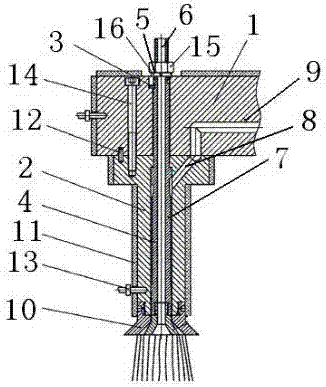
[0038] A melt electrospinning device, comprising an upper nozzle body 1 and a lower nozzle body 2, the upper nozzle body 1 is provided with an upper nozzle inner cylinder 3, the lower nozzle body 2 is provided with a lower nozzle inner cylinder 4, and the upper nozzle inner cylinder 3 and the lower nozzle inner cylinder 4 are set correspondingly and the axes coincide; the top of the upper nozzle body 1 is provided with a socket 5, and the core liquid pipe 6 is inserted through the socket 5 through the upper nozzle body 1 and the lower nozzle body 2, and the core liquid pipe 6 is located at The axes of the upper nozzle inner cylinder 3 and the lower nozzle inner cylinder 4 coincide; the core fluid pipeline 6 has a core fluid cavity inside, and the outer wall of the core fluid pipeline 6 is sealed with the inner walls of the upper nozzle inner cylinder 3 and the lower nozzle inner cylinder 4 The skin liquid chamber 7, the upper part of the lower nozzle body 2 is provided with a c...


PUM

PropertyMeasurementUnit
surface areaaaaaaaaaaa

Abstract

An electrostatic melt spinning device comprises an upper nozzle and a lower nozzle. An upper-nozzle inner barrel is formed in the upper nozzle, a lower-nozzle inner barrel is formed in the lower nozzle, and a liquid core pipeline penetrates the upper nozzle and the lower nozzle; a concave and convex anti-adhesion structure is arranged on inner walls of parts connected with a molten polymer in spinning, and an anti-adhesion function of a polymer melt in spinning assemblies can be achieved; the function mechanism of the concave and convex anti-adhesion structure lies in that the concave and convex anti-adhesion structure includes concave parts and convex parts, the convex parts are arranged in a manner of protruding internal surfaces of the parts, direct contact of the polymer melt with highadhesion and internal walls of the parts is reduced by the aid of supporting among points, a gas suspension function is formed under the action of the high-temperature high-pressure melt, and self-separated anti-adhesion is achieved.

Description

technical field [0001] The invention relates to the technical field of textiles, in particular to a novel melt electrostatic spinning device. Background technique [0002] The earliest record of the melt spinning process comes from a British patent in 1845. In 1939, melt spinning was industrialized as a production process for the manufacture of nylon 66 fibers. Such as figure 1 As shown, the basic process of melt spinning includes melting of materials, extrusion from the micropores of the spinneret, and cooling and solidification of melt streams. The finished filament can be wound into a bobbin or otherwise processed. In the process of melt spinning, the polymer is fed into the extruder, conveyed by the screw, plasticized, melted and then forwarded to the metering accumulator: the metering polymer ensures that the melt of the polymer can flow stably and evenly into the In the spinning assembly of the key component, the melt in the spinning assembly is filtered by the fil...

Claims


Application Information

Patent Timeline
Patent Type & Authority Applications(China)
IPC IPC(8): D01D5/00
Inventor 钟海炎
Owner TONGXIANG YIZHIJIANNENG INFORMATION TECH
Why Eureka
Try Eureka