
Rainwater storage tank ejection-type flushing device, control method and rainwater storage tank

A technology for flushing devices and storage tanks, which is applied in water supply devices, waterway systems, cleaning sewer pipes, etc. It can solve the problems of not being able to clean the bottom of the pool, easy to produce dead ends, time-consuming and labor-intensive cleanliness, etc., to achieve convenient and fast installation, The effect of high cleaning degree and low maintenance cost

Inactive Publication Date: 2018-01-12
WUHAN SHENGYU DRAINING SYST
View PDF5 Cites 2 Cited by
  • Summary
  • Abstract
  • Description
  • Claims
  • Application Information

AI Technical Summary

Problems solved by technology

[0003] However, after the initial rainwater entering the rainwater storage tank has been stored for a period of time, a large amount of sediment will be deposited on the bottom of the tank. After the sewage is emptied, the bottom of the tank must be washed clean in time, otherwise, once the sediment on the bottom of the tank is compacted, it will be difficult to clear
In the prior art, water pipes are generally used on the ground to flush the bottom of the rainwater storage tank, but this flushing method requires the use of water pipes to reintroduce the water source to flush the bottom of the pool, and the second is to flush the bottom of the pond on the ground , time-consuming and labor-intensive and the cleanliness is not high
Moreover, during the flushing process, due to the high distance between the water pipe and the bottom of the pool, it is easy to produce dead angles during flushing, and the bottom of the rainwater storage tank cannot be rinsed clean.

Method used


Image

  • Rainwater storage tank ejection-type flushing device, control method and rainwater storage tank
  • Rainwater storage tank ejection-type flushing device, control method and rainwater storage tank
  • Rainwater storage tank ejection-type flushing device, control method and rainwater storage tank

Examples


Embodiment Construction

[0028] The present invention will be further described in detail below in conjunction with the accompanying drawings and specific embodiments to facilitate a clear understanding of the present invention, but they do not limit the protection scope of the present invention.

[0029] In the description of the present invention, it should be noted that the terms "first", "second" and so on are only used for descriptive purposes, and do not indicate or imply relative importance.

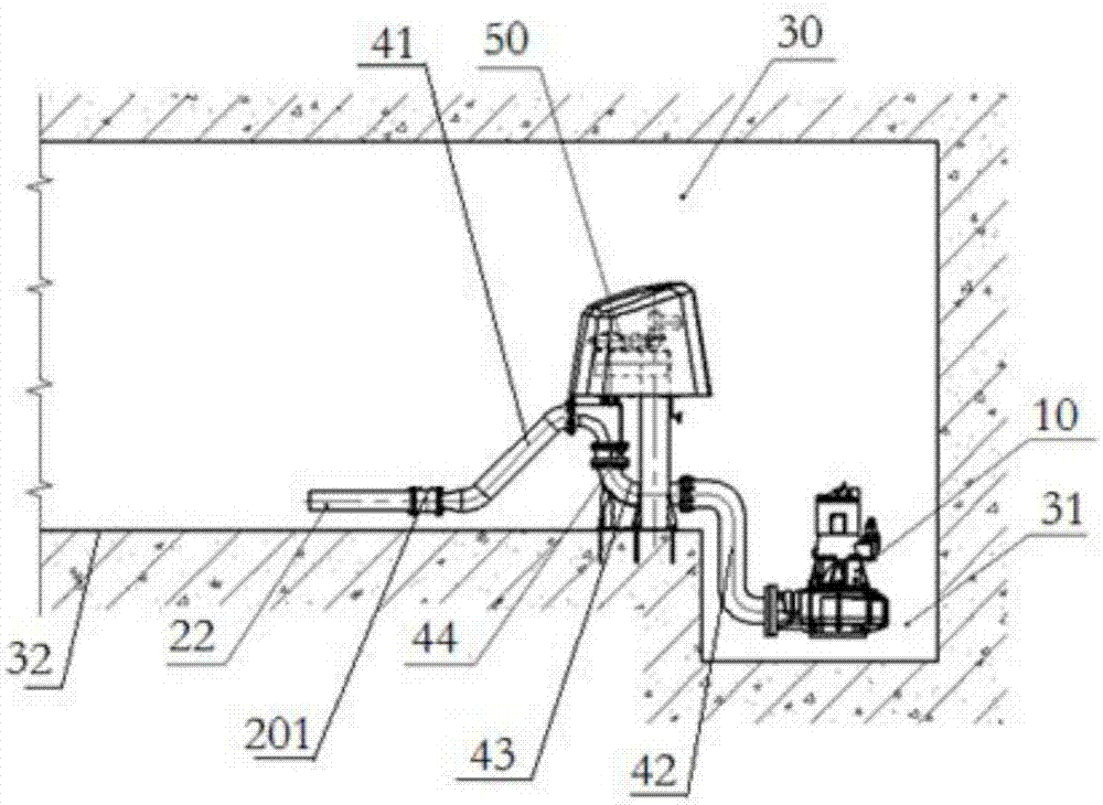
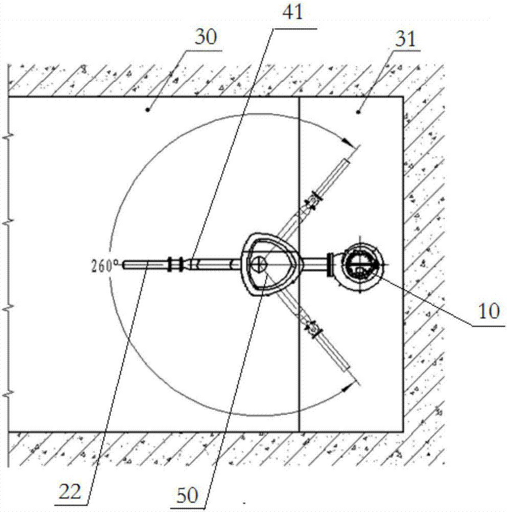
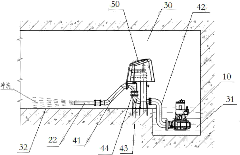
[0030] Such as Figure 1 to Figure 4 As shown, the jet flushing device for the rainwater storage tank includes: a power pump 10 and a rotary driver 50 arranged in the sump 31 . The power pump 10 is used to transport the rainwater in the sump 31 to the spray pipe 22 , and then spray it onto the second surface 32 of the rainwater storage tank 30 to wash it. The rotary driver 50 is used to drive the spray pipe 22 to rotate in the rainwater storage tank 30 .

[0031] The flushing device can use the power pu...


PUM


Abstract

The invention discloses a rainwater storage tank ejection-type flushing device, a control method and a rainwater storage tank. The rainwater storage tank ejection-type flushing device comprises a power pump and a rotating driver, the power pump is arranged in a water collection pit and used for delivering rainwater in the water collection pit into an ejection pipe to be ejected onto the second surface of the rainwater storage tank to flush the same, and the rotating driver is used for driving the ejection pipe to rotate in the rainwater storage tank. The flushing device can utilize the power pump to extract water in the water collection pit to vigorously flush the bottom in the rainwater storage tank when sewage in the rainwater storage tank is about to be drained. In the process of ejection-type flushing, the ejection pipe can rotate within a range of 0-260 degrees (namely being adjustable), in other words, the ejection pipe can rotate underwater to eject water flow, so that the flushing device is wide in flushing range, and the bottom of the rainwater storage tank can be cleaned in an omnibearing manner and can be flushed more cleanly.

Description

technical field [0001] The invention relates to the technical field of sewage treatment, in particular to a jet-type flushing device for a rainwater storage tank, a control method and the rainwater storage tank. Background technique [0002] When a city receives rain, it tends to increase runoff, and rainwater and sewage often converge, increasing the burden on urban drainage and sewage pipe networks. Direct discharge into natural water bodies will cause serious pollution to the water body environment. Therefore, it is necessary to add rainwater storage tanks and other facilities to regulate and treat rainwater with different water qualities. In my country's urban drainage system, the application of rainwater storage tanks is becoming more and more extensive. [0003] However, after the initial rainwater entering the rainwater storage tank has been stored for a period of time, a large amount of sediment will be deposited on the bottom of the tank. After the sewage is emptie...

Claims


Application Information

Patent Timeline
Patent Type & Authority Applications(China)
IPC IPC(8): E03F9/00
Inventor 姜景升
Owner WUHAN SHENGYU DRAINING SYST
Learn More