Sliding formwork component and open caisson blade foot layer sliding formwork construction method applying sliding formwork component

A construction method and sliding form technology, which are applied in the fields of formwork/formwork/work frame, on-site preparation of building components, infrastructure engineering, etc., can solve the problem that the solid section of the cutting edge is not easy to handle, the construction period is long, and the noise is easy to disturb the people. and other problems, to achieve the effect of speeding up the construction speed and overall stiffness, saving construction period and labor input, and solving the problem of water seepage

Pending Publication Date: 2018-01-12
中铁科建有限公司
View PDF8 Cites 18 Cited by
  • Summary
  • Abstract
  • Description
  • Claims
  • Application Information

AI Technical Summary

Problems solved by technology

Traditional cast-in-place construction requires a large number of formwork and supports, and occupies a large area, and the construction period is long. The finished line shape and appearance quality are not easy to control. The noise generated by the construction of a large number of steel formwork is likely to disturb the residents.
[0003] The invention patent with application number 2017100964937 discloses an engineering method for a prefabricated spliced ​​caisson type parking garage, such as figure 1 As shown, the caisson structure includes the bottom blade layer 1' and several standard layers 2' above. The installation accuracy of the blade layer 1' determines the assembly quality of the upper caisson standard layer 2'. The blade layer 1' The construction method is: place the cutting edge block vertically, and splicing several cutting edge blocks in sequence to form the first layer of the wellbore (the lower part of the inner wall of the cutting edge block is inclined downward to connect with the outer wall to form a wedge-shaped section), and the method of vertical placement is to pass The support frame, positioning limiter, and diagonal brace jointly support the blade foot block. After the installation of the first blade foot block is completed, the support frame, positioning limiter, and diagonal brace are removed. This construction method adopts a prefabricated assembly blade foot structure, because the components are Special-shaped structure, large volume, transportation, hoisting and turnover need two to three times, high cost, and a large number of auxiliary support brackets are required for assembly, the accuracy of the splicing seam is not easy to guarantee, and the solid section of the blade foot is not easy to handle in the later stage of waterproofing

Method used


Image

  • Sliding formwork component and open caisson blade foot layer sliding formwork construction method applying sliding formwork component
  • Sliding formwork component and open caisson blade foot layer sliding formwork construction method applying sliding formwork component
  • Sliding formwork component and open caisson blade foot layer sliding formwork construction method applying sliding formwork component

Examples


Embodiment Construction

[0038] In order to make the object, technical solution and advantages of the present invention clearer, the invention will be further described in detail below in conjunction with the accompanying drawings and embodiments.

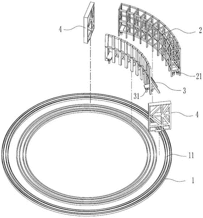
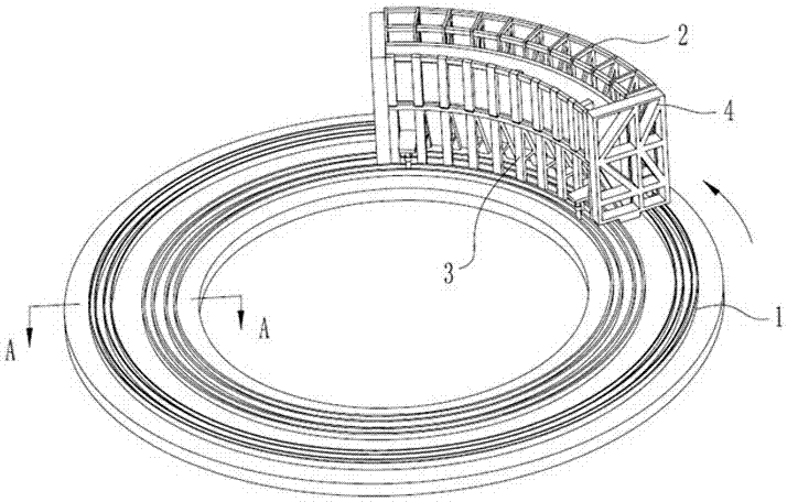
[0039] Such as figure 2 As shown, the present invention discloses a sliding form component, which includes a slideway 1, an outer formwork 2, an inner formwork 3, two side forms 4, an upper tie bar 5, a bottom tie bar 6, and several connecting and fixing pieces.

[0040] A plurality of chutes 11 for the installation of the outer formwork 2 and the inner formwork 3 are arranged on the slideway 1, and the slideway 1 can be formed by assembling a plurality of curved concave-shaped steels.

[0041] In this embodiment, the slideway 1 is a ring-shaped slideway, and an outer ring-shaped chute and an inner ring-shaped chute are arranged on the ring-shaped slideway. The outer formwork 2 and the inner formwork 3 are an arc-shaped structure on the ring. Legs 21, th...


PUM


Abstract

The invention discloses a sliding formwork component. The sliding formwork component comprises a sliding way, an outer template, an inner template, two side templates and a plurality of connecting fixing pieces. The sliding way is provided with a plurality of sliding grooves for installation of the outer template and the inner template. A plurality of outer stand bars are arranged at the bottom ofthe outer template. The outer stand bars are arranged on the outer side of the sliding way and can be installed and move along the sliding grooves. A plurality of inner stand bars are arranged at thebottom of the inner template. The inner stand bars are arranged on the inner side of the sliding way and can be installed and move along the sliding grooves. The side templates are arranged on the two side edges of the inner template and the two side edges of the outer template and are connected with the inner template and the outer template through the connecting fixing pieces. The invention further discloses an open caisson blade foot layer sliding formwork construction method. The method comprises the steps of field leveling, sliding way installing, steel bar bundling, template installing,concrete pouring, side template dismounting, template sliding and the like. According to the sliding formwork component and the method, the linear vertical perpendicularity after blade foot construction is finished can be ensured, and accordingly the assembling quality of upper-layer open caisson standard segments is guaranteed.

Description

technical field [0001] The invention relates to the technical field of building construction, in particular to a sliding form component and a sliding form construction method. Background technique [0002] As a part of the structural foundation, the caisson is often designed and implemented as a temporary structure, and its construction method is mostly completed by one-time or staged cast-in-place on site, and there are few prefabricated assembled structures. Traditional cast-in-place construction requires a large number of formwork and supports, and occupies a large area, and the construction period is long. The finished line shape and appearance quality are not easy to control, and the noise generated by the construction of a large number of steel formwork is likely to disturb the residents. [0003] The invention patent with application number 2017100964937 discloses an engineering method for a prefabricated spliced ​​caisson type parking garage, such as figure 1 As sho...

Claims


Application Information

Patent Timeline
Patent Type & Authority Applications(China)
IPC IPC(8): E04G11/34E02D23/00
Inventor 李世清李斯海李宏涛张义冬李婵夕余光中苏钊艺
Owner 中铁科建有限公司
Why Eureka
Try Eureka