A Compensation Method for Laser Flatness Measurement Error

A compensation method and measurement error technology, applied in the direction of measurement devices, optical devices, instruments, etc., to achieve the effect of improving projection accuracy

Inactive Publication Date: 2017-12-12
杭州鼎热科技有限公司
View PDF7 Cites 0 Cited by
  • Summary
  • Abstract
  • Description
  • Claims
  • Application Information

AI Technical Summary

Problems solved by technology

[0006] In order to overcome many technical problems caused by the traditional large-scale surface flatness detection system, the present invention provides a method for implementing laser flatness measurement error compensation

Method used


Image

  • A Compensation Method for Laser Flatness Measurement Error
  • A Compensation Method for Laser Flatness Measurement Error
  • A Compensation Method for Laser Flatness Measurement Error

Examples


Embodiment Construction

[0043] In conjunction with the accompanying drawings, the present invention will be described in detail below.

[0044] 1. Main technical ideas

[0045] A laser flatness measurement error compensation method involved in the present invention, the main technical idea is that it is composed of three parts: sub-pixel image scattering compensation, reference inclination compensation, and spot variation centering compensation, which can effectively improve the laser flatness measurement system. measurement accuracy.

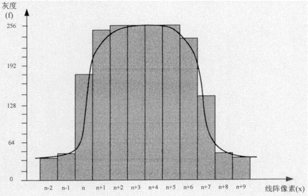
[0046] The sub-pixel image scattering compensation involved in the above technical route is to use the pixel edge recognition method to solve the scattering problem of the laser beam due to long-distance transmission, which can ensure the vertical accuracy of the plane measurement.

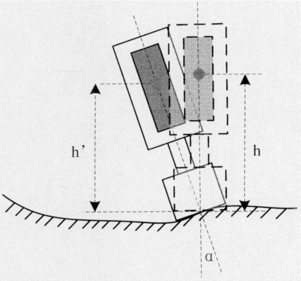
[0047]The reference inclination compensation involved in the above technical route uses the method of inclination transformation height to solve the problem of reference deviation in las...


PUM


Abstract

A laser flatness measurement error compensation method is characterized in that it consists of three parts: sub-pixel image scattering compensation, reference inclination angle compensation, and light spot variation centering compensation, which can effectively improve the measurement accuracy of a laser flatness measurement system. The sub-pixel image scattering compensation uses the pixel edge recognition method to solve the scattering problem of the laser beam due to long-distance transmission, which can ensure the vertical accuracy of the plane measurement. The reference inclination compensation uses the method of inclination transformation height to solve the problem of the reference deviation of laser target placement, which can ensure the height reference of the laser target. The spot variation centering compensation uses the reciprocating micro-movement method to solve the problem that the size of the laser spot varies with the change of the target distance, and improves the projection accuracy of the laser spot.

Description

technical field [0001] The invention relates to the fields of plane detection and surface topography evaluation, in particular to a method for implementing laser flatness measurement error compensation. Background technique [0002] With the continuous development of science and technology, the competition in modern industry is becoming increasingly fierce, product upgrading is accelerating, and precision requirements are constantly increasing. The continuous emergence of various new technologies, materials, and processes has brought great impact to the design, processing, testing, and control of modern industrial equipment. Flatness is one of the most basic equipment manufacturing and testing technical indicators, and its technical requirements are constantly improving, especially in the fields of special equipment such as metallurgy, mining, electric power, aerospace, aviation, ships and large molds. [0003] Flatness, also known as flatness, refers to the deviation of th...

Claims


Application Information

Patent Timeline
Patent Type & Authority Patents(China)
IPC IPC(8): G01B11/30
Inventor 陈尚俭郑俊谭大鹏
Owner 杭州鼎热科技有限公司
Why Eureka
Try Eureka