Eureka AIR delivers breakthrough ideas for toughest innovation challenges, trusted by R&D personnel around the world.

Foam-assisted gravity oil driving method

An auxiliary gravity and foam technology, which is applied in the direction of earthwork drilling, production fluid, wellbore/well components, etc., to achieve the effects of improving sweep coefficient, inhibiting gas channeling, and improving oil washing efficiency

Inactive Publication Date: 2018-01-12
CHINA UNIV OF PETROLEUM (EAST CHINA)
View PDF5 Cites 11 Cited by
  • Summary
  • Abstract
  • Description
  • Claims
  • Application Information

AI Technical Summary

Problems solved by technology

[0004] Aiming at the insufficiency of the existing gas-assisted gravity flooding effect, the present invention provides a foam-assisted gravity flooding method, which improves the sweep coefficient and oil washing efficiency, thereby increasing the oil production of the oil well

Method used


Image

  • Foam-assisted gravity oil driving method
  • Foam-assisted gravity oil driving method

Examples


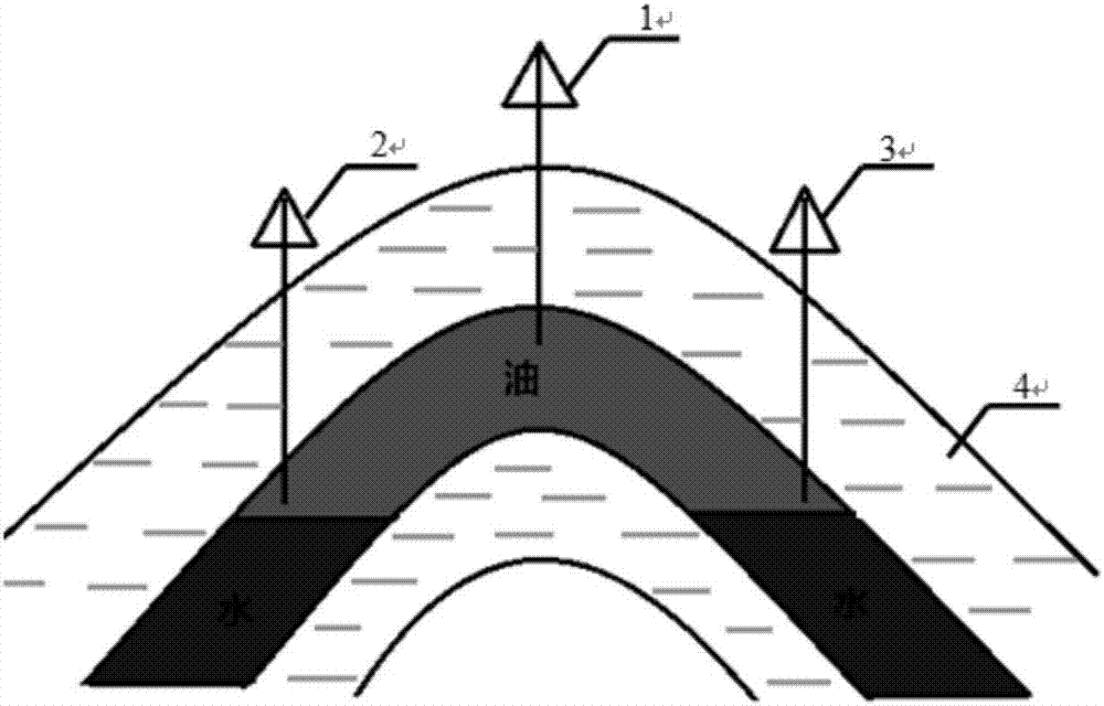
Embodiment 1

[0026] There are natural fractures in semi-anticline structural oil reservoirs, which are cut and sealed by faults, and the formation dip angle is about 15°. After water flooding, the water content of the produced oil has reached more than 90%.

[0027] A foam-assisted gravity flooding method for semi-anticline structure reservoirs. A horizontal well is drilled inside the oil-water transition zone as a production well, and a vertical well is drilled at the top of the reservoir as an injection well. The pre-generated oil is continuously injected from the injection well at the top of the reservoir. Foam, the volume injected into the foam is 0.05PV, the quality of the foam is 70%, and the concentration of the foaming agent is 1%. Because the foam has the property of selectively blocking high-permeability bands or cracks, it can effectively control gas channeling. Moreover, the foam can play a good role in profile control, so that the foam can enter more low-permeability parts, so ...

Embodiment 2

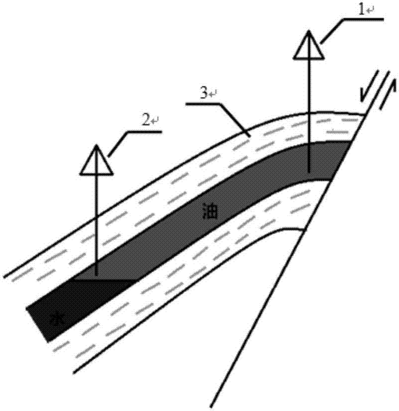
[0029] There are natural fractures in the Duanbi structural oil reservoir, which are cut and sealed by faults, and the formation dip angle is about 15°. After water flooding, the water content of the produced oil has reached more than 90%.

[0030] A foam-assisted gravity flooding method for a faulted-nose structure reservoir. A vertical well is drilled inside the oil-water transition zone as a production well, and a vertical well is drilled at the top of the reservoir as an injection well, and the pre-generated foam is continuously injected from the injection well at the top of the reservoir. The volume of the injected foam is 0.12PV, the mass of the foam is 65%, and the concentration of the foaming agent is 0.6%. Because the foam has the property of selectively blocking hyperpermeable bands or cracks, it can effectively control gas channeling. Moreover, the foam can play a good role in profile control, so that the foam can enter more low-permeability parts, so that the high a...


PUM


Abstract

The invention relates to a foam-assisted gravity oil driving method. The foam-assisted gravity oil driving method comprises the steps that a well is drilled as a production well at the lower part of an oil reservoir, a straight well is drilled as an injection well at the top of the oil reservoir, foam is continuously injected into the injection well, and the foam injection volume is controlled tobe 0.01-0.2 PV, oil is pushed in high and low permeable parts by using the foam, after being broken, the foam is accumulated to form a secondary gas cap to displace top attic oil, so that the more foam can enter the low permeable part, the high and low permeable parts achieve the effect of simultaneous propulsion, and sweep coefficient is improved; after the foam is broken, released gas enters thehigh part of a structure under the action of gravity differentiation, the gas is gathered continuously to form the secondary gas cap, the top attic oil is displaced, and the sweep coefficient is further improved; and a surfactant in a foam system can greatly reduce interfacial tension of oil and water, so that original oil in a restrained state becomes flowable oil, and the oil washing efficiencyis improved.

Description

technical field [0001] The invention relates to a foam-assisted gravity flooding method, which belongs to the technical field of oil and gas field development engineering. Background technique [0002] Judging from the structural characteristics of China's oil and gas reservoirs and the properties of crude oil, some oil reservoirs belong to light oil reservoirs with anticline structures, fault nose structures, and buried hill structures. Most of these oil and gas reservoirs have the characteristics of deep burial, large reservoir dip, thick oil layers, and low crude oil viscosity. Some also have original air cap and edge bottom water. After years of water flooding in this type of reservoir, “attic oil” often remains at the top of the reservoir. At the same time, there are high water-cut bands after water flooding, making it difficult to further effectively produce medium and weak water flooded layers. Gas-assisted gravity flooding is an effective method for exploiting rema...

Claims


Application Information

Patent Timeline
Patent Type & Authority Applications(China)
IPC IPC(8): E21B43/16
Inventor 李宾飞黄梦梅刘坤李兆敏杨勇李翔李松岩
Owner CHINA UNIV OF PETROLEUM (EAST CHINA)
Why Eureka
Eureka Blog
Learn More