A friction plate return mechanism and an air pressure disc brake with the mechanism

A technology of return mechanism and friction plate, applied in the direction of brake type, axial brake, gear transmission mechanism, etc., can solve the problems of complex assembly of pneumatic disc brakes, increase of air pressure of brake air chambers, difficulty in popularization and use, etc. Achieve simple structure, prolong service life and solve the effect of dragging

Active Publication Date: 2021-08-31
CHERY AUTOMOBILE CO LTD
View PDF7 Cites 0 Cited by
  • Summary
  • Abstract
  • Description
  • Claims
  • Application Information

AI Technical Summary

Problems solved by technology

But the only shortcoming is that the return of the friction plate of the pneumatic disc brake adopts natural return, and the friction plate is returned by the rotation of the brake disc. There is no active return structure, which will cause the following problems: There is always dragging between the friction plate and the brake disc, which will cause a series of problems such as friction plate wear, noise, and increased fuel consumption
[0003] In order to solve the above problems, technicians have added a return mechanism for the friction plate on the air disc brake, mainly using springs to control the return of the friction plate, such as the patent No. 201510437414. Its friction plate active return method", and the "air pressure disc brake automatic return device" disclosed in the patent No. 201420665802.X, etc., but this method increases the brake air chamber required for braking The air pressure (because of the elastic force of the return spring to overcome), and the assembly of the air disc brake is more complicated, so it is difficult to popularize and use

Method used


Image

  • A friction plate return mechanism and an air pressure disc brake with the mechanism
  • A friction plate return mechanism and an air pressure disc brake with the mechanism
  • A friction plate return mechanism and an air pressure disc brake with the mechanism

Examples


Embodiment 1

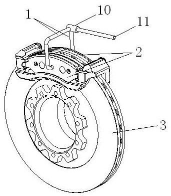
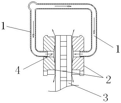
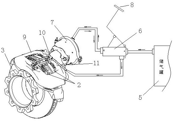
[0026] Such as figure 1 , 2 As shown, the friction plate return mechanism of this embodiment is composed of an air pipe 1, two friction plates 2 that are relatively arranged and movable relative to each other, and a brake disc 3 located between the two friction plates 2; Both are provided with a straight cylinder-shaped ventilation pipeline 4, and the positions of the ventilation pipeline 4 on the two friction plates 2 are opposite; the ventilation pipeline 4 extends along the movement direction of the friction plate 2, and the diameter of the air pipe 1 is slightly smaller than the ventilation pipeline 4 The air pipe 1 extends from the outer side of the friction plate 2 into the ventilation pipeline 4, and the side of the ventilation pipeline 4 facing the brake disc 3 has a trumpet-shaped structure. In this embodiment, the air pipes 1 corresponding to the two friction plates are connected to the main air pipe 11 through the three-way valve 10 .

[0027] The return principle...


PUM


Abstract

The purpose of the present invention is to provide a friction plate return mechanism with simple structure and without affecting the braking force of the friction plate and an air pressure disc brake with the return mechanism. The friction plate return mechanism of the present invention is composed of an air pipe, two friction plates that are relatively arranged and movable relative to each other, and a brake disc located between the two friction plates; One side of the rotor is the intake section extending along the moving direction of the friction plate, and the side of the ventilation pipeline facing the brake disc is the air outlet section; the air pipe extends from the outer side of the friction plate to the intake section of the ventilation pipeline. The air storage tank in the pneumatic disc brake of the present invention is connected with the air inlet of the brake distribution valve, the air outlet of the brake distribution valve is connected with the brake air chamber, the brake distribution valve is controlled by the brake pedal, and the compressed air To drive the caliper, thereby driving the friction plate to move relatively to achieve braking; the key is that the air intake end of the air pipe of the friction plate return mechanism is connected with the exhaust gas outlet of the brake distribution valve.

Description

technical field [0001] The invention belongs to the technical field of automobile chassis brake application, and in particular relates to a brake system of an automobile. Background technique [0002] With the development of technology, pneumatic disc brakes are increasingly used in large commercial vehicles to replace traditional drum brakes. Compared with drum brakes, air disc brakes have better stability and thermal decay performance. But the only shortcoming is that the return of the friction plate of the pneumatic disc brake adopts natural return, and the friction plate is returned by the rotation of the brake disc. There is no active return structure, which will cause the following problems: There is always dragging between the friction plate and the brake disc, which will cause a series of problems such as friction plate wear, noise, and increased fuel consumption. [0003] In order to solve the above problems, technicians have added a return mechanism for the frict...

Claims


Application Information

Patent Timeline
Patent Type & Authority Patents(China)
IPC IPC(8): F16D65/22F16D65/18F16D55/224F16D121/02F16D125/02
Inventor 常立晔林巧云康云庆陈庆东
Owner CHERY AUTOMOBILE CO LTD
Why Eureka
Try Eureka