Shielding container
A technology for shielding a container and a container body, which is applied in the field of ray scanning inspection equipment, can solve problems such as inconvenience in adjusting the position of a ray generator, and achieve the effects of stable and reliable moving process, simple structure and improved accuracy
- Summary
- Abstract
- Description
- Claims
- Application Information
AI Technical Summary
Problems solved by technology
Method used
Image
Examples
Embodiment 1
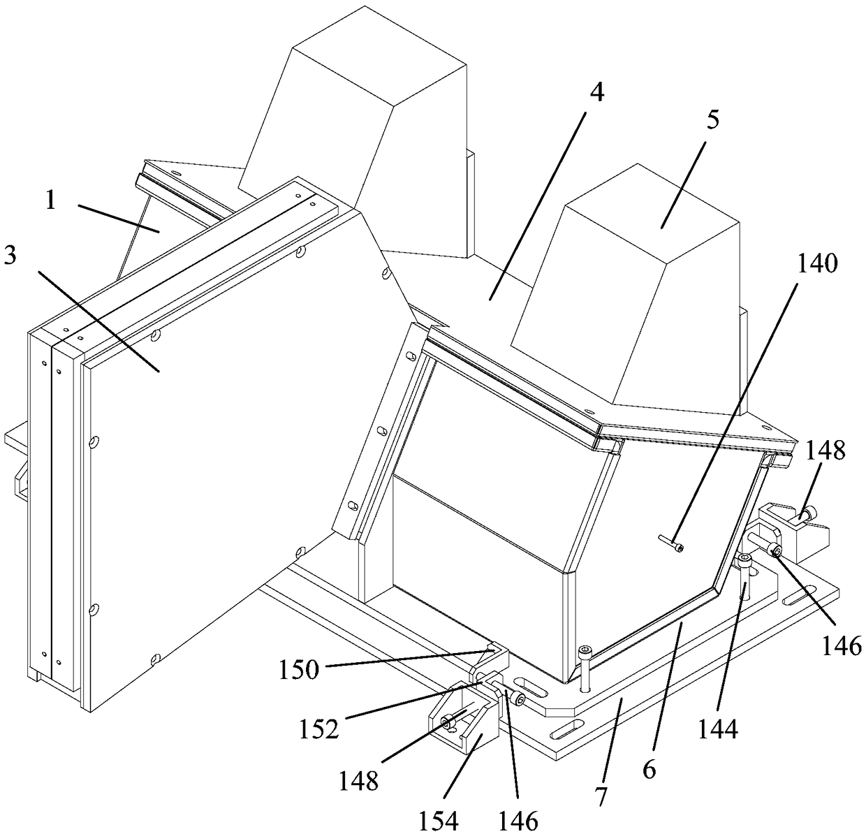
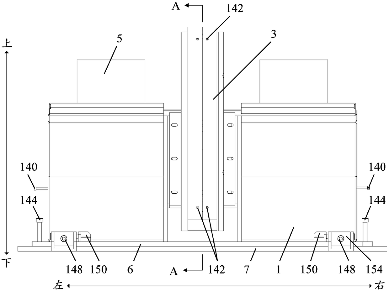
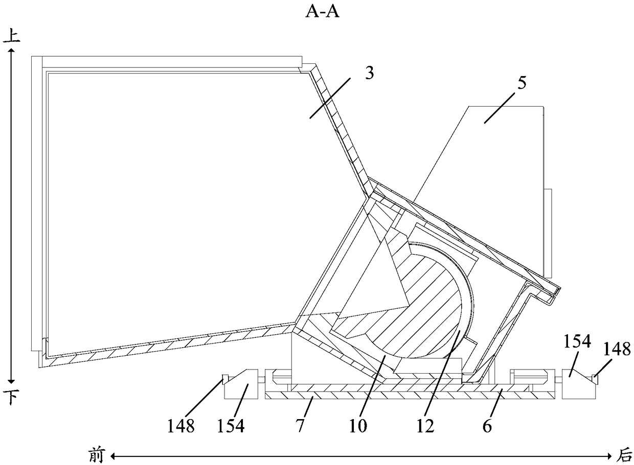
[0051] Such as Figure 1 to Figure 5 As shown, the shielded container according to an embodiment of the present invention includes a container body 1 and a plurality of bottom plates stacked on the bottom of the container body 1 in turn; the top of the container body 1 is provided with an opening, and the container body 1 is also provided with a Install the installation cavity of the ray generator 2, the installation cavity communicates with the opening, so that the ray generator 2 is put into the installation cavity through the opening for installation; as image 3 As shown, in the installation cavity, there is an installation bracket 10 fixedly connected with the bottom of the shielding container, and the radiation generator 2 is installed on the installation bracket 10, and the radiation generator band 12 connected with the installation bracket 10 is used for circumferential Fix to prevent the ray generator 2 from coming off. A ray outlet communicating with the installatio...
Embodiment 2
[0074] The difference between this embodiment and Embodiment 1 is that four abutting parts 150 are arranged on the first bottom plate 6, which are distributed on the first bottom plate 6 outside the container body 1 in a cross shape, wherein the front and rear ends of the container body 1 The two abutting portions 150 are arranged symmetrically, and the two abutting portions 150 at the left and right ends are arranged symmetrically; the first boss 152 and the second boss 154 are both arranged on the second bottom plate 7 .
[0075] Specifically, a first boss 152 is respectively provided on the second bottom plate 7 at the left and right ends of the container body 1, and a fourth adjusting bolt 146 is arranged on the first boss 152, and the fourth adjusting bolt 146 is arranged along the container body 1. It runs through the first boss 152 longitudinally, and leans against the abutting parts 150 at the left and right ends of the container body 1 to adjust the longitudinal positi...
Embodiment 3
[0077] The difference between this embodiment and Embodiment 1 is that only the first bottom plate 6 is provided, and the first bottom plate 6 is not fixedly connected to the container body 1 , but placed under the container body 1 .
[0078] Specifically, the four third adjusting bolts 144 are arranged at the bottom of the container and lean against the first base plate 6; the four third adjusting bolts 144 can be rotated in the same range to adjust the up and down position of the container body 1; The inclination angle of the container body 1 can be adjusted by rotating the third adjusting bolt 144 in different ranges.
[0079] Two first bosses 152 and two second bosses 154 are respectively arranged on the first bottom plate 6 outside the container body 1 in a cross shape, and the fourth adjusting bolts 146 on the two first bosses 152 are connected with the container respectively. The left and right ends of the body 1 abut; the fifth adjusting bolts 148 on the two second bos...
PUM
 Abstract
Description
Claims
Application Information
 - R&D
- Intellectual Property
- Life Sciences
- Materials
- Tech Scout
- Unparalleled Data Quality
- Higher Quality Content
- 60% Fewer Hallucinations
Browse by: Latest US Patents, China's latest patents, Technical Efficacy Thesaurus, Application Domain, Technology Topic, Popular Technical Reports.
© 2025 PatSnap. All rights reserved.Legal|Privacy policy|Modern Slavery Act Transparency Statement|Sitemap|About US| Contact US: help@patsnap.com


