
Air conditioning system

A technology for air conditioning systems and heat exchangers, which is applied to lighting and heating equipment, irreversible cycle compressors, and compressors with reversible cycles, etc., which can solve the problem of limited space for the air supply aperture of the sliding vane and reduced efficiency of the main cylinder compression process. , It is difficult to supply gas with large flow and other problems

Active Publication Date: 2018-01-12
GREE ELECTRIC APPLIANCES INC
View PDF4 Cites 11 Cited by
  • Summary
  • Abstract
  • Description
  • Claims
  • Application Information

AI Technical Summary

Problems solved by technology

However, from the point of view of the compression process, the compression process of parallel compression belongs to single-stage compression. When operating in low temperature and ultra-low temperature conditions with a large pressure ratio, the pressure ratio exceeds the range of the general single-stage compression pressure ratio, resulting in the compression process of the main cylinder. Efficiency drops rapidly
[0004] In addition, due to the simple structure and low cost of the single-cylinder air supply technology, it has gradually received attention in recent years. In the patent with the publication number CN105673510A, a rolling rotor compressor with air supply through sliding vanes is proposed. The disadvantage is that it is thin and slippery. Adding air supply channels and check valves inside the slide will reduce the strength of the slide. At the same time, due to the limited air supply aperture space inside the slide, the flow resistance is large, and it is difficult to achieve a small pressure difference in a short time when the back pressure is high. Large flow air supply

Method used


Image

  • Air conditioning system
  • Air conditioning system
  • Air conditioning system

Examples


no. 1 example

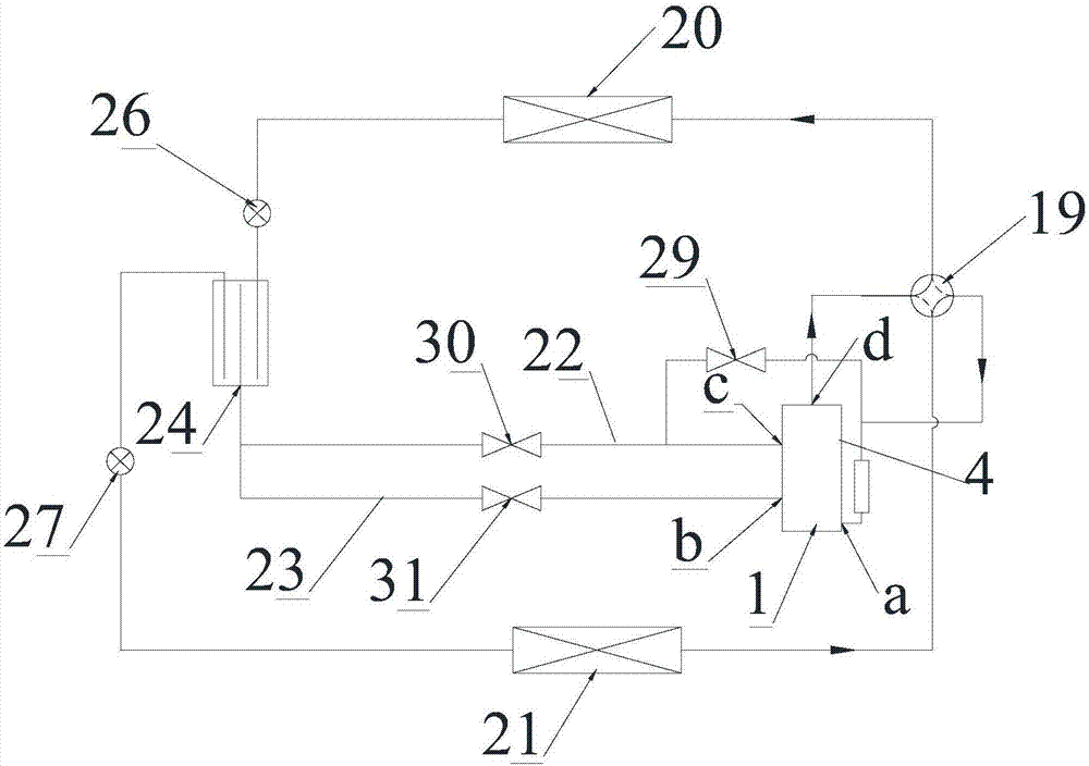
[0040] see in conjunction figure 1 As shown, according to the first embodiment of the present invention, the air supply device includes a first flasher 24, the inlet of the first flasher 24 is connected to the first heat exchanger 20, and the liquid outlet of the first flasher 24 is connected to To the second heat exchanger 21 , the gas outlets of the first flasher 24 are respectively connected to the first gas supply branch 22 and the second gas supply branch 23 .

[0041] After the refrigerant enters the first flasher 24, it is flashed by the first flasher 24 to form a large amount of gaseous refrigerant, and this part of gaseous refrigerant enters the compressor from the first gas supply branch 22 through the second suction port c , Supplement air to the compressor to increase enthalpy, improve the compression performance of the compressor, and improve the working performance of the air conditioner.

[0042] In the above embodiment, during the working process of the air co...


PUM


Abstract

The invention provides an air conditioning system. The air conditioning system comprises a compressor, a four-way valve, a first heat exchanger, a second heat exchanger, a throttling device and an airfeeding device; the compressor comprises a first air sucking port, a second air sucking port, an exhaust port, an air feeding port and a pump body module; the pump body module comprises a first cylinder and a rotor; the first cylinder is provided with a first air sucking inlet, a first exhaust outlet, an air feeding inlet, an air feeding channel, a first slide piece and a first slide piece groove; a first end of the first slide piece butts against the periphery of the rotor to divide a compression cavity into an air sucking cavity and an exhaust cavity; when the air feeding channel and the first air sucking inlet are commonly connected to the air sucking cavity, the air feeding channel is closed; and when the air feeding channel and the first exhaust outlet are commonly connected to the exhaust cavity, the air feeding channel is opened when the air feeding pressure is higher than or equal to the pressure in the exhaust cavity, and is closed when the air feeding pressure is lower thanthe pressure in the exhaust cavity. The air conditioning system can prevent the air feeding backflow, meanwhile, guarantees the strength of the slide piece, and reduces the air feeding resistance.

Description

technical field [0001] The invention belongs to the technical field of air conditioning, and in particular relates to an air conditioning system. Background technique [0002] The existing two-stage rotor compression mostly adopts the form of two cylinders connected in series to supplement air in the middle. The compression and air supply process is as follows: the refrigerant compressed by the low-pressure stage cylinder is discharged through the exhaust outlet, mixed with the supplementary air, and then enters the high-pressure stage cylinder. further compression. From this process, it can be seen that most refrigerants need to go through two suction and two exhaust processes, and mix with supplementary air in the middle chamber, so there is flow resistance loss and mixing loss. [0003] In order to solve this problem, parallel compression technology came into being. The so-called parallel compression technology is to set up two cylinders with different volumes—the main c...

Claims


Application Information

Patent Timeline
Patent Type & Authority Applications(China)
IPC IPC(8): F25B1/10F25B13/00F25B41/04F25B41/06F04C29/00F04C29/12F25B41/20F25B41/30
CPCY02B30/70
Inventor 郑波潘俊梁祥飞黄柏良
Owner GREE ELECTRIC APPLIANCES INC
Learn More