Workpiece roughness detection device

A detection device and flatness technology, applied in measurement devices and instruments, using ultrasonic/sonic/infrasonic waves, etc., can solve the problems of high physical strength requirements of workers, worker fatigue, and large detection volume, so as to achieve a fast and simple detection process and simplify work. The process and operation are simple and easy

Pending Publication Date: 2018-01-12
JIANGSU HONGBAO FORGING
View PDF0 Cites 4 Cited by
  • Summary
  • Abstract
  • Description
  • Claims
  • Application Information

AI Technical Summary

Problems solved by technology

[0003] However, there are many problems in manual detection as follows: 1. The amount of detection is large, and the physical strength requirements for workers are relatively high; 2. Workers are prone to fatigue, and frequent missed detections, false detections, and even sorting errors

Method used


Image

  • Workpiece roughness detection device
  • Workpiece roughness detection device
  • Workpiece roughness detection device

Examples


Embodiment

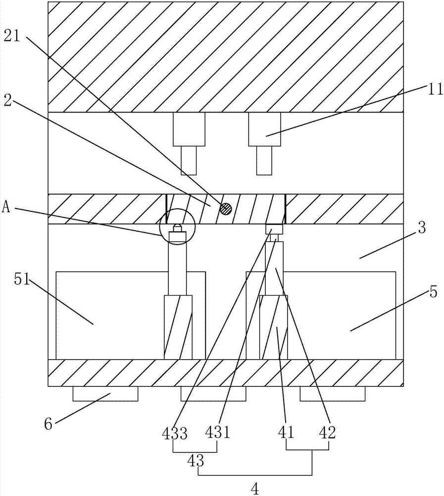
[0027] Embodiment: a kind of workpiece flatness detection device, such as figure 1 As shown, it includes a detection platform 1, a robot grasper (not shown in the figure) for realizing workpiece transportation, and a detection computer. On the detection platform 1, a detection board 2 for placing workpieces is provided, and a detection computer is provided in the detection board 2. The vibration sensor 21 connected to the circuit signal is located on the detection platform 1 directly above the detection board 2 and is provided with a driving device 11 connected to the detection computer circuit signal. The driving device 11 can realize linear motion up and down, and is placed on the detection board 2 The workpiece on the top generates pressure, and the driving device 11 can adopt a structure such as a combination transmission of a hydraulic cylinder, a DC servo motor, and a rack and pinion transmission mechanism.

[0028] Such as Figure 4 As shown, the detection computer inc...

specific Embodiment approach

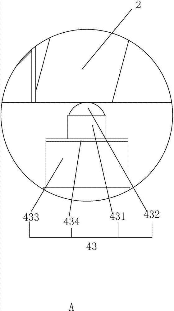
[0031] Specific implementation method: first control a plurality of power cylinders 41, make its telescopic rod 42 stretch out fully so that the detection plate 2 is in a state of being flush with the upper surface of the detection platform 1, and then the detection computer controls the electromagnet 434 to work, so that the support sleeve The upper surface of 433 is adsorbed and contacted with the bottom of the detection board 2 to form a support for the detection board 2, so that the detection board 2 is placed stably in a horizontal state. At this time, the workpiece to be detected is placed on the detection board 2 by the manipulator, and the driving device is controlled. 11 works, the control module in the detection computer transmits a pressure value signal to the drive device 11, the drive device 11 works and applies a certain pressure to the workpiece, and the pressure value is the pressure value set in the detection computer.

[0032] Such as Figure 5 with 6 As sho...


PUM


Abstract

The invention discloses a workpiece roughness detection device. The device comprises a detection table and a detection computer, a detection plate used for putting a workpiece is arranged on the detection table, a vibration sensor connected with the detection computer is arranged in the detection plate, and drive devices which act on the workpiece and apply pressure on the workpiece are arranged at the position, over the detection plate, of the detection table. A space is formed in the detection table, a plurality of supporting devices are arranged at the positions, at the two ends, on the bottom surface of the detection plate in a hinged mode, each supporting device comprises power air cylinders which are fixedly arranged at the positions, at the two ends of the detection plate, in the space, a telescoping rod of each power air cylinder is fixedly provided with a connecting mechanism which is connected with the bottom of the detection plate, and a waste box and a storage box are arranged at the positions, at the two ends of the detection plate, in the detection table respectively. By means of the detection device, the workpiece roughness can be quickly detected, the detection process is reliable, the detection efficiency is high, the accuracy is high, and the labor stress and cost are reduced.

Description

technical field [0001] The invention relates to the field of workpiece detection, in particular to a workpiece flatness detection device. Background technique [0002] The engine connecting rod is one of the core components of the engine system. The flatness of the connecting rod is an important quality indicator. Usually, the factory manually places the connecting rod on the platform. Because there will be a gap between the uneven connecting rod and the platform, the connecting rod After the force movement, a vibrating sound wave of a specific frequency will be generated, and the manual judges whether it is an uneven product or not according to the sound wave. [0003] However, there are many problems in manual detection as follows: 1. The amount of detection is large, and the physical strength requirements for workers are relatively high; 2. Workers are prone to fatigue, and missed detection, false detection often occur, and even sorting errors occur. [0004] Therefore, ...

Claims


Application Information

Patent Timeline
Patent Type & Authority Applications(China)
IPC IPC(8): G01B17/08B07C5/34
Inventor 袁海平朱剑峰丁平峰
Owner JIANGSU HONGBAO FORGING
Why Eureka
Try Eureka