
A Sparse Imaging Method for Intermittent Synthetic Aperture Radar with Coprime Downsampling
A synthetic aperture radar and sparse imaging technology, which is applied to instruments, measurement devices, utilizing re-radiation, etc., can solve the problems affecting the image quality of synthetic aperture radar, and achieve the goal of improving the quality of sparse imaging, facilitating system implementation, and suppressing the level of side lobes. Effect
- Summary
- Abstract
- Description
- Claims
- Application Information
AI Technical Summary
Problems solved by technology
Method used
Image

Examples
Embodiment Construction
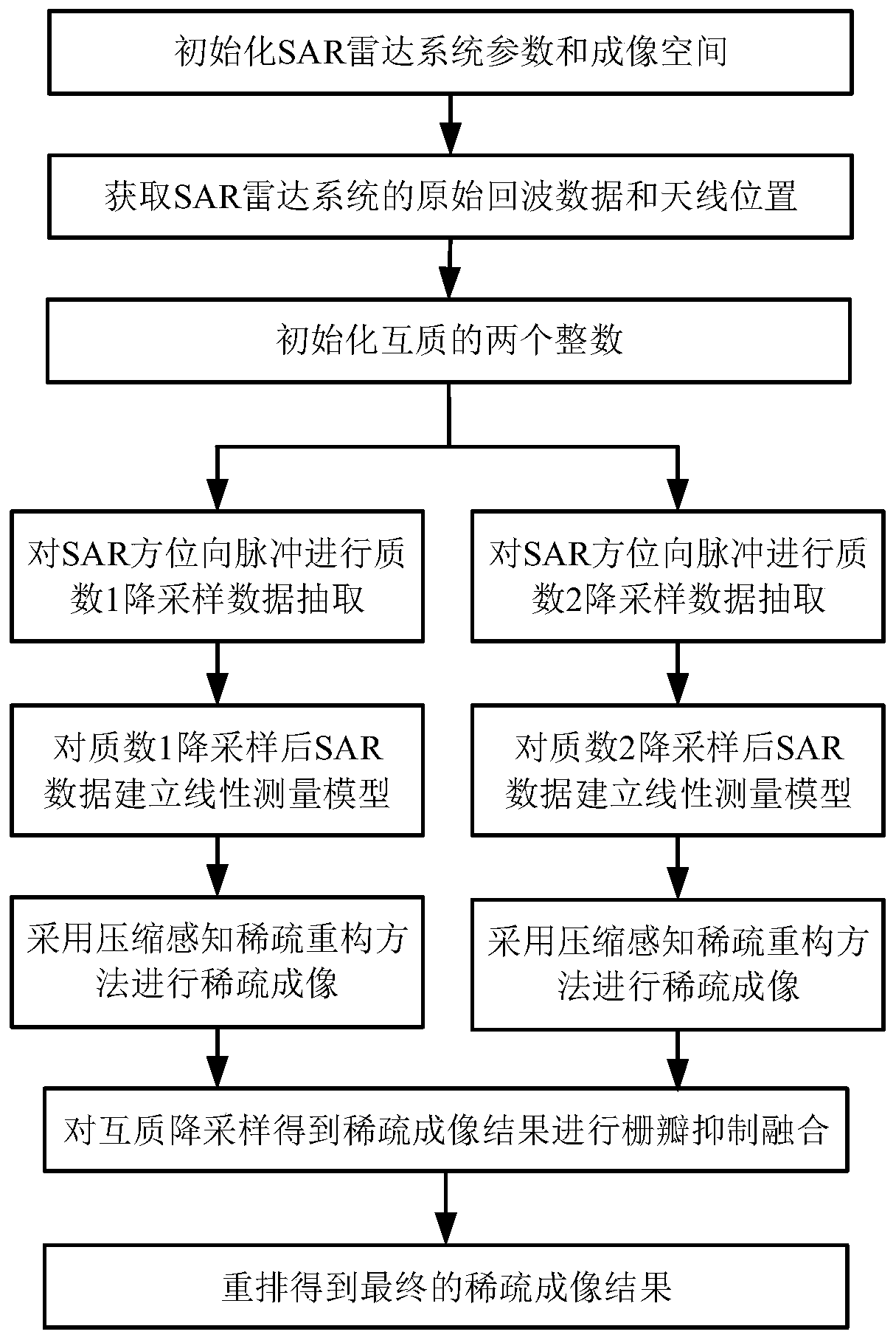
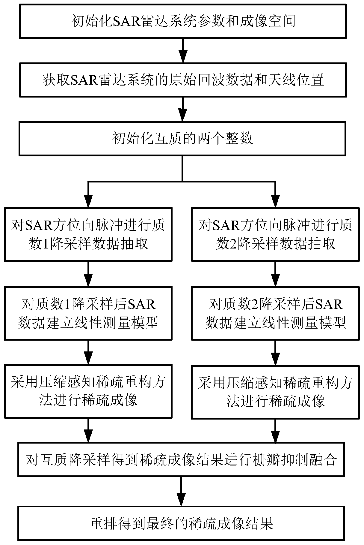
[0048] The present invention mainly adopts the method of simulation experiment for verification, and all steps and conclusions are verified correctly on MATLAB R2014b software. The specific implementation steps are as follows:
[0049] Step 1. Initialize SAR radar system parameters and imaging space:
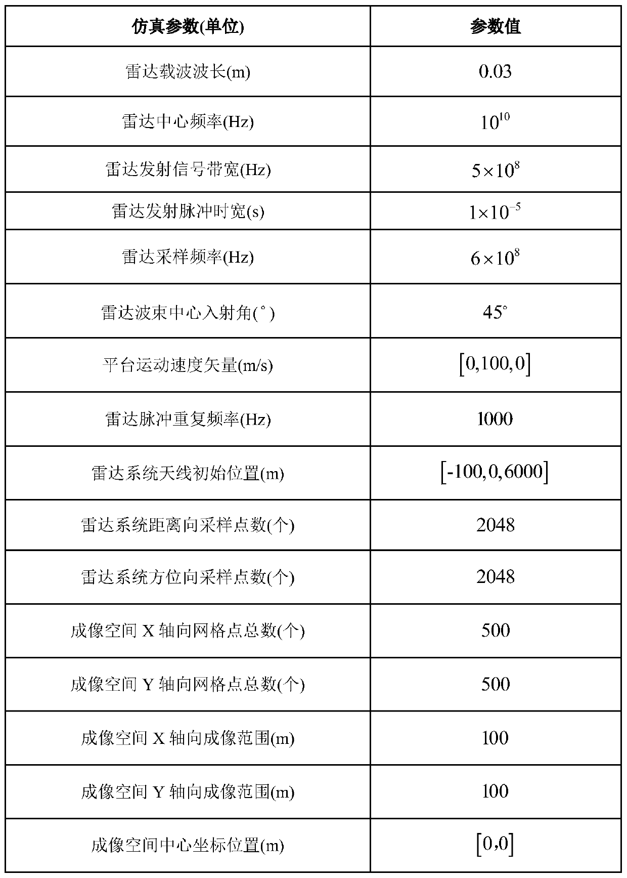
[0050] Initialize SAR radar system parameters, including: radar carrier wavelength λ = 0.03m, radar center frequency f 0 = 10 10 Hz, radar emission signal bandwidth B=5×10 8 Hz, the time width of radar pulse T r =10- 5 s, radar sampling frequency F s =6×10 8 Hz, the incident angle of the radar beam center θ=45°, the radar pulse repetition frequency PRF=1000 Hz, the platform movement velocity vector V r =[0,100,0]m / s, the number of sampling points in the range of the radar system N r =2048, the number of sampling points in the azimuth direction of the radar system N a = 2048, the initial position of the radar system antenna P S (0)=[-100,0,6000]m;
[0051] Initialize the SAR imaging spa...
PUM
 Abstract
Description
Claims
Application Information