Optical emitter and optical module

An optical transmitter and a technology for emitting light, applied in the field of optical communication, can solve the problems of long coupling time and low yield of optical transmitters, and achieve the effect of short coupling time

Inactive Publication Date: 2018-01-12
HISENSE BROADBAND MULTIMEDIA TECH
View PDF2 Cites 16 Cited by
  • Summary
  • Abstract
  • Description
  • Claims
  • Application Information

AI Technical Summary

Problems solved by technology

[0005] In view of this, the present application provides an optical transmitter and an optical module...

Method used


Image

  • Optical emitter and optical module
  • Optical emitter and optical module
  • Optical emitter and optical module

Examples


Embodiment Construction

[0031] In order to make the purpose, technical solutions and advantages of the embodiments of the present invention clearer, the technical solutions in the embodiments of the present invention will be clearly and completely described below in conjunction with the drawings in the embodiments of the present invention. Obviously, the described embodiments It is a part of embodiments of the present invention, but not all embodiments. Based on the embodiments of the present invention, all other embodiments obtained by persons of ordinary skill in the art without creative efforts fall within the protection scope of the present invention.

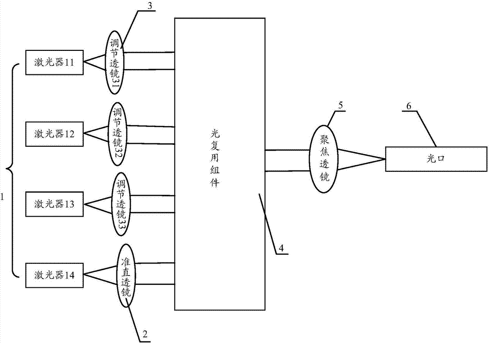
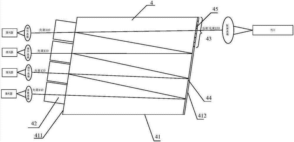
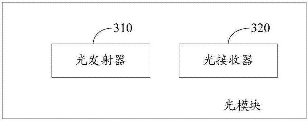
[0032] The present application provides an optical transmitter and an optical module to solve the problems of low yield rate and long coupling time of existing optical transmitters.

[0033] The technical solution of the present application will be described in detail below with specific embodiments. The following specific embodiments may be comb...


PUM


Abstract

The invention provides an optical emitter and an optical module. The optical emitter comprises a laser array, a collimating lens and adjustment lenses; the collimating lens is arranged on the emissionoptical path of one laser, the adjustment lenses are arranged on the emission optical paths of other lasers, and the collimating lens and the adjustment lenses are distributed in a non-linear mode inthe array direction; an optical multiplex component which synthetizes multiple paths of light beams into a path of light beam is arranged on the emergence optical paths of the collimating lens and the adjustment lenses, a focusing lens is arranged on the emergence optical path of the optical multiplex component, and an optical port is formed in the emergence optical path of the focusing lens; thecollimating lens is used for collimating light beams emitted by the lasers and making the collimated light beams irradiate into the optical port through the optical multiplex component and the focusing lens; the adjustment lenses are used for making the light beams emitted by the lasers irradiate into the optical multiplex component in the mode parallel to the collimated light beams. The opticalemitter and the optical module are high in yield and short in coupling time.

Description

technical field [0001] The present application relates to the field of optical communication, in particular to an optical transmitter and an optical module. Background technique [0002] In the field of high-speed data communication, due to the speed bottleneck of electrical transmission, for optical fiber communication networks with a transmission rate of 40 / 100Gbps, in order to ensure long-distance high-speed transmission of data, optical transmitters are generally used to transmit multiple optical signals of different wavelengths. Coupled into single-mode fiber for transmission. For example, an optical transmitter is used to couple 4 optical signals of different wavelengths into a single-mode optical fiber for transmission. [0003] In the existing 4-way multiplexing optical transmitter, when coupling 4-way optical signals into the optical fiber, it is necessary to couple the 4-way optical signals separately, find out the position of the optical fiber adapter when the op...

Claims


Application Information

Patent Timeline
IPC IPC(8): G02B6/42G02B6/293
Inventor 唐永正杜光超
Owner HISENSE BROADBAND MULTIMEDIA TECH
Why Eureka
Try Eureka