

Method and device for calibrating clock frequency
A clock frequency and frequency technology, applied in pulse processing, pulse generation, electrical components, etc., can solve problems such as oscillator clock frequency deviation, circuit function error, oscillator frequency error, etc., to reduce impact, improve accuracy, reduce The effect of power consumption
- Summary
- Abstract
- Description
- Claims
- Application Information
AI Technical Summary
Problems solved by technology
Method used
Image

Examples
Embodiment Construction
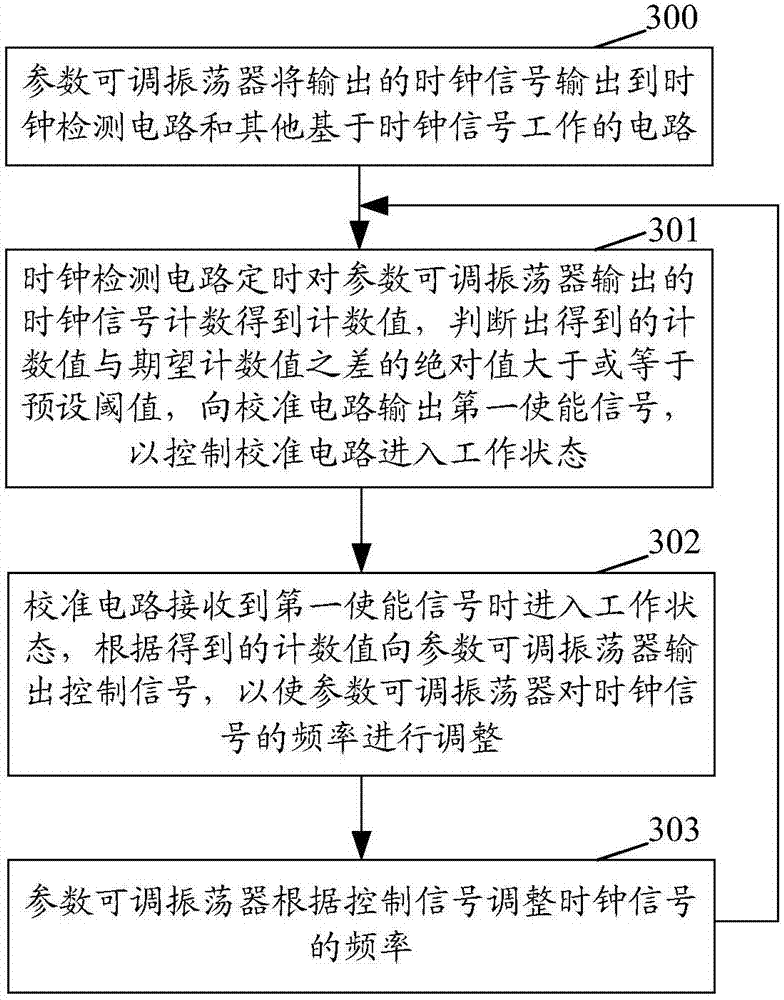
[0056] Embodiments of the present invention will be described in detail below in conjunction with the accompanying drawings. It should be noted that, in the case of no conflict, the embodiments in the present application and the features in the embodiments can be combined arbitrarily with each other.
[0057] The steps shown in the flowcharts of the figures may be performed in a computer system, such as a set of computer-executable instructions. Also, although a logical order is shown in the flowcharts, in some cases the steps shown or described may be performed in an order different from that shown or described herein.
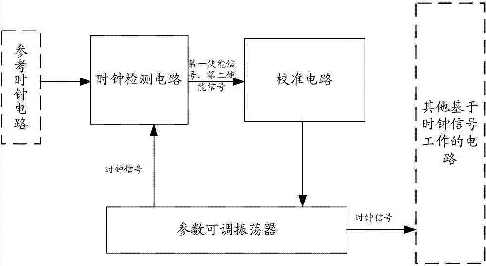
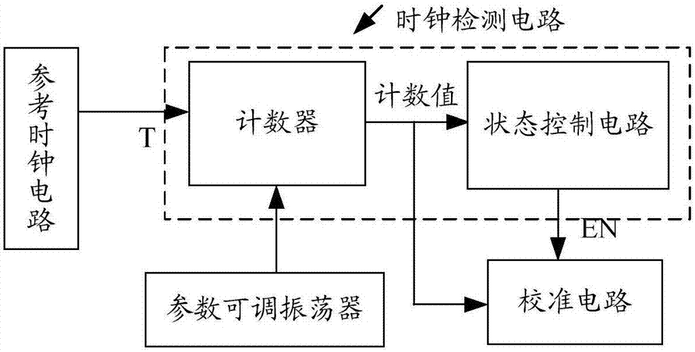
[0058] see figure 1 , the embodiment of the present invention proposes a device for calibrating the clock frequency, including:
[0059] The clock detection circuit is used to regularly count the clock signal output by the parameter adjustable oscillator to obtain a count value, judge that the absolute value of the difference between the obtained count valu...
PUM
 Abstract
Description
Claims
Application Information