
Uplink antenna selection method and device

An antenna selection and antenna technology, applied in the field of communication, can solve the problems of weak switching gain and performance, reducing the accuracy and reliability of antenna reception, and increasing the error rate of antenna selection, so as to improve accuracy and reliability, ensure gain and Performance, effects of good voice and data services

Active Publication Date: 2018-01-12
ZTE CORP
View PDF6 Cites 2 Cited by
  • Summary
  • Abstract
  • Description
  • Claims
  • Application Information

AI Technical Summary

Problems solved by technology

The open-loop antenna selection technology does not take advantage of channel changes, and the user device only periodically switches the uplink signal transmission antenna repeatedly, which is weak in switching gain and performance; and in the case of high-speed mobile UE, the closed-loop antenna selection technology is due to the rapid channel change. , the delay in the feedback process will cause the channel state when the uplink antenna is selected to be different from the state at the time of feedback, resulting in an increase in the error rate of antenna selection. In the closed-loop antenna selection technology, the selection switching time is relative to CSI (Channel State Information, channel state information) feedback. Delay will undoubtedly lead to changes in the real state of the channel, and the more the UE moves at a high speed, the more obvious this change will be. Some data show that when the UE moves faster than 120km / h, the error rate of the feedback information of the closed-loop feedback scheme will reach 10%, greatly reducing the accuracy and reliability of antenna reception

Method used

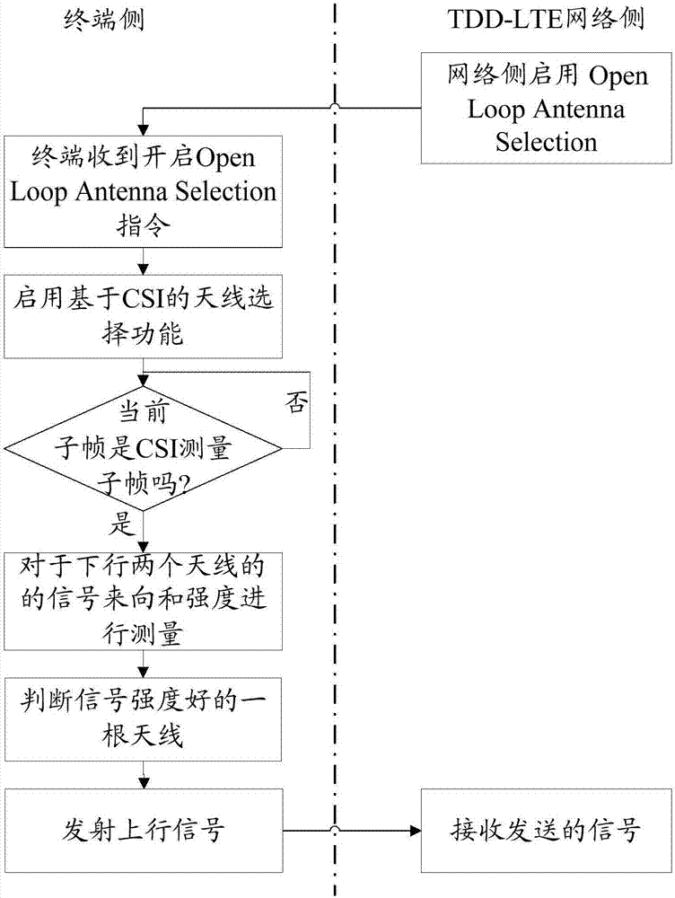

Image

  • Uplink antenna selection method and device
  • Uplink antenna selection method and device
  • Uplink antenna selection method and device

Examples


Embodiment Construction

[0044] It should be understood that the specific embodiments described here are only used to explain the present invention, not to limit the present invention.

[0045] The invention provides a method for selecting an uplink antenna.

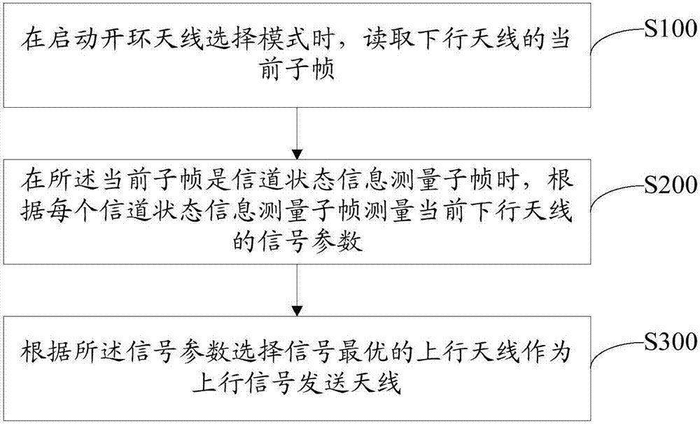
[0046] refer to figure 1 , figure 1 It is a schematic flowchart of the first embodiment of the uplink antenna selection method of the present invention, the uplink antenna selection method includes:

[0047] Step S100, when the open-loop antenna selection mode is enabled, read the current subframe of the downlink antenna.

[0048] Step S200, when the current subframe is a channel state information measurement subframe, measure the signal parameters of the current downlink antenna according to each channel state information measurement subframe.

[0049] As an implementation manner, the UE measures the signal parameters of the current downlink antenna according to the CSI measurement subframe of the downlink antenna, and acquires the channel s...

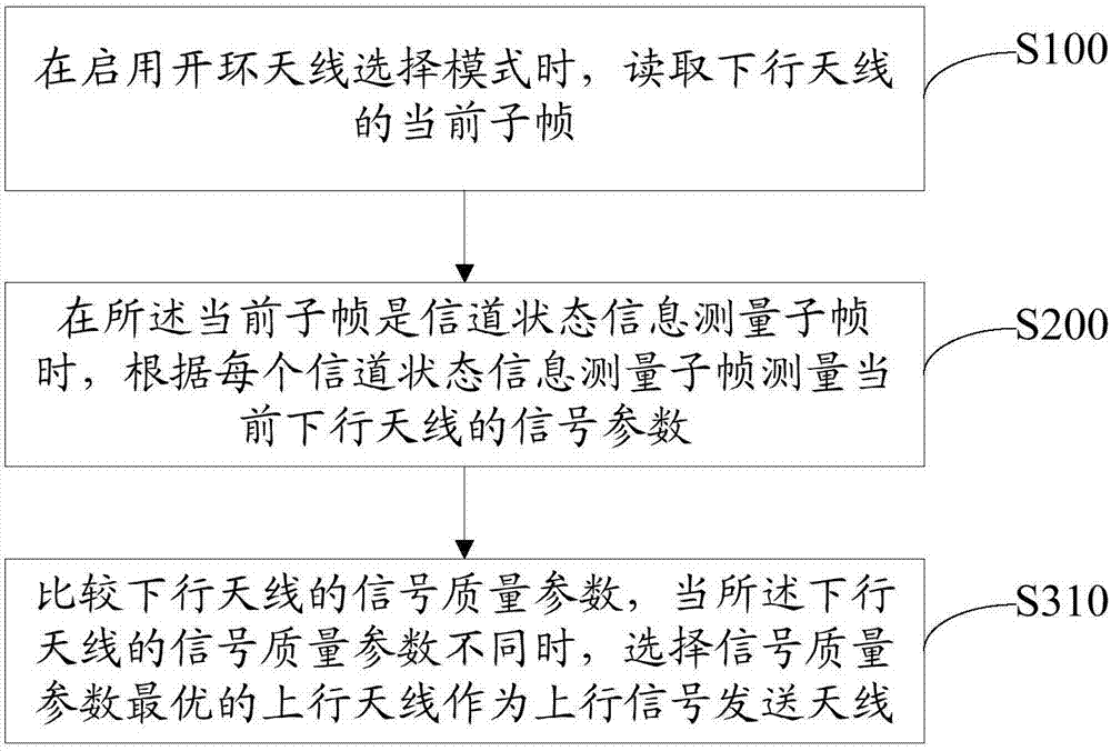

PUM


Abstract

The invention discloses an uplink antenna selection method and device. The method comprises the steps of reading the current subframe of a downlink antenna when an open loop antenna selection mode isstarted; measuring the signal parameters of the current downlink antenna according to each channel state information measurement sub-frame when the current sub-frame is the channel state information measurement sub-frame; and selecting an uplink antenna with optimal signals according to the signal parameters as an uplink signal transmission antenna. The invention further discloses an uplink antenna selection device. According to the method, the gain and the performance of the antenna can be ensured, and the accuracy and the reliability of the information reported by a terminal in the high-speed moving state can be improved, so that a user can obtain better voice and data services.

Description

technical field [0001] The present invention relates to the field of communication technology, in particular to an uplink antenna selection method and device. Background technique [0002] In the LTE (Long Term Evolution, Long Term Evolution) technology of 3GPP (3rd Generation Partnership Project, the third generation partnership project), according to different duplex modes, the LTE system can be divided into LTE-FDD (Frequency Division Duplexing, frequency division dual In these two duplex modes, the RRC (Radio Resource Control, radio resource control) layer on the network side can control whether the UE (User Equipment, user terminal) Enable the selection of the uplink antenna and specify the uplink antenna selection mode, and the UE selects different uplink antennas in different modes to send uplink signals to the network side. [0003] At present, LTE supports uplink antenna selection technology. The uplink antenna selection technology defined in the 3GPP standard can ...

Claims


Application Information

Patent Timeline
Patent Type & Authority Applications(China)
IPC IPC(8): H04B7/06
CPCH04B7/06H04B17/00
Inventor 邢树先高明刚
Owner ZTE CORP
Learn More