
Precision seeding device for beans

A technology for precise sowing and mass seeding, which is applied in the field of precision seeding devices for beans, can solve the problems of low sowing accuracy, limited use site, and high use cost, achieves improved speed and accuracy, and avoids multicast and missed sowing , the effect of improving work efficiency

Inactive Publication Date: 2018-01-16
CHONGQING MAOXU SCI & TECH
View PDF0 Cites 2 Cited by
  • Summary
  • Abstract
  • Description
  • Claims
  • Application Information

AI Technical Summary

Problems solved by technology

[0002] The seeder is an important tool in agricultural production. The traditional seeder is composed of a sowing part and a fertilization part. Each monomer corresponds to a row. Each sowing mechanism is equipped with a seed box and a fertilizer box separately. In order to increase the fertilizer load and reduce the manufacturing cost, several seeding mechanisms share a fertilizer box and then discharge fertilizer separately. However, for mechanical seeders for bean sowing and fertilization, most of the existing mechanical seeders are Belt conveying and vacuum negative pressure suction cups are used to achieve rapid sowing. Although the sowing speed is improved, the sowing accuracy is low, and there are a large number of multi-seeding, missed sowing and insufficient suction leading to random seeding, which greatly increases farmers. The work burden of lack of seed, equal seeding and replanting; in addition, these mechanical seeders are expensive, poor in quality, high in failure rate, and limited in use space, resulting in high cost of use

Method used


Image

  • Precision seeding device for beans
  • Precision seeding device for beans
  • Precision seeding device for beans

Examples


Embodiment Construction

[0021] The preferred embodiments of the present invention will be described in detail below with reference to the accompanying drawings.

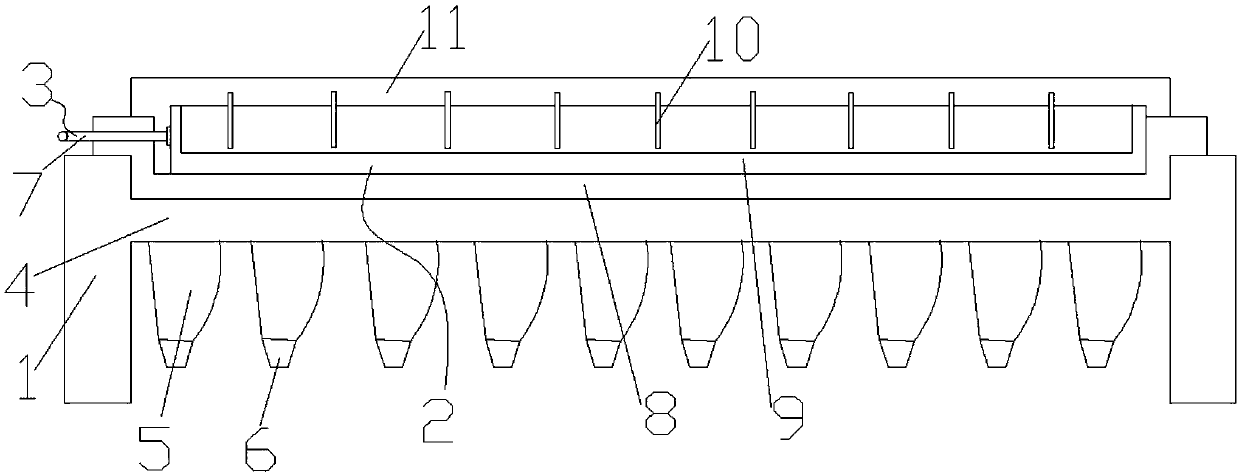
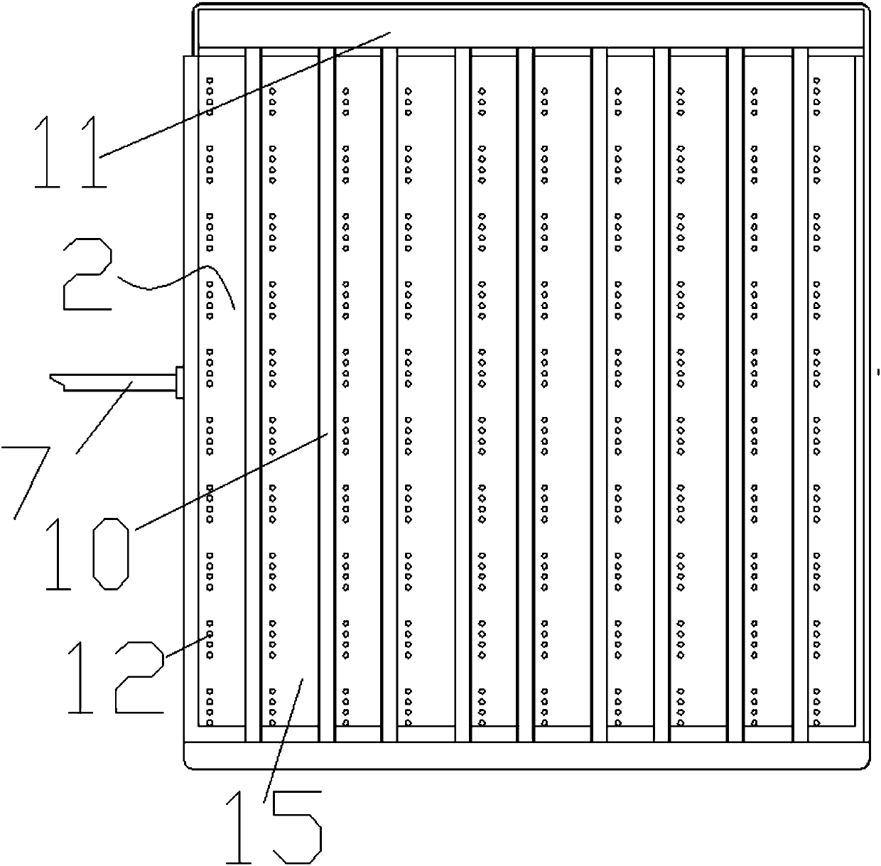
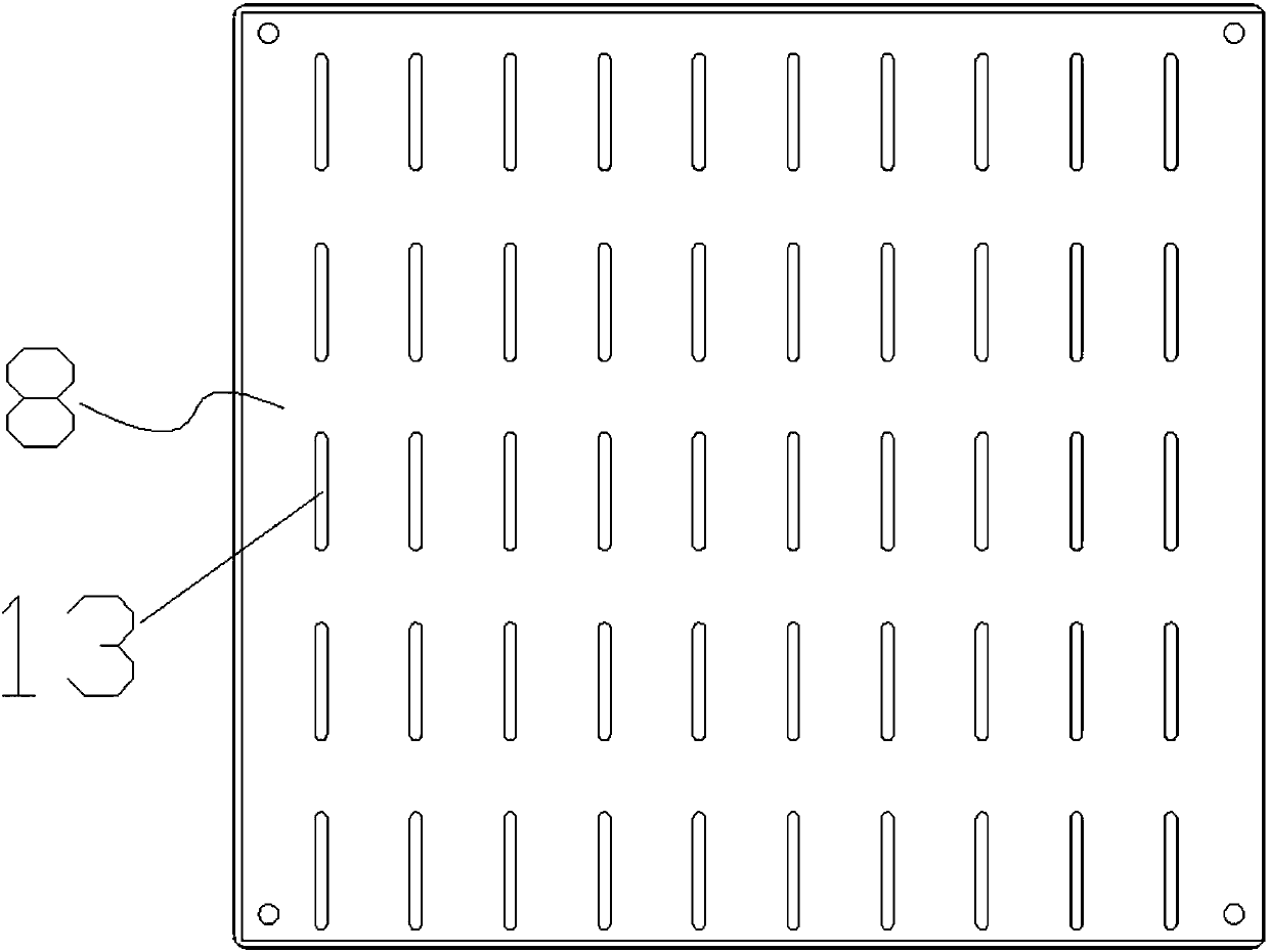
[0022] Such as Figure 1-5 Shown is the structural representation of the bean precision sowing device of the present invention; The present invention a kind of bean precision sowing device of the present invention, comprises frame 1, the seed measuring device 2 that is arranged on frame 1 and push-pull mechanism 3, so The frame is provided with a mounting plate 4 for fixing the seed measuring device 2, and the seed measuring device 2 includes a chassis 8, side weirs 1 arranged on the front and rear sides of the chassis 8, and a seed measuring plate 9 slidingly arranged on the chassis 8 1. The side weir II arranged on the left and right sides of the seed measuring plate 9 and no less than 2 seed retaining plates 10 erected between a pair of side weirs I, the side weir II on one side of the seed measuring plate 9 and the push-pull mechanism ...


PUM


Abstract

The invention discloses a precision seeding device for beans. The device comprises a rack, a seed metering device and a push-pull mechanism, wherein a mounting plate is arranged on the rack, the seedmetering device comprises a base plate, base plate weirs I, seed metering plates, seed metering plate weirs II and seed blocking plates, the seed metering plate weirs II are connected with the push-pull mechanism, seed storage grooves are defined by adjacent seed blocking plates and seed metering plates, a row of seed metering holes are formed in the position, close to the corresponding seed blocking plate and located in each seed storage groove, in each seed metering plate, seed metering grooves which are in one-to-one correspondence to 3 or 4 seed metering holes in each seed metering plate are uniformly distributed in the base plate, and seed receiving bins communicated with the seed metering grooves in a one-to-one correspondence manner and hole forming cones arranged at the bottoms ofthe seed receiving bins are mounted at the bottom of the mounting plate. The precision seeding device is simple in structure, low in cost and capable of being operated manually and automatically, theseed metering plates can store and meter seeds quickly through movement of the push-pull mechanism, the seeding speed and accuracy is increased, excessive seeding and missing seeding are avoided, seedmetering turnover time is saved, and the seeding efficiency of farmers is improved.

Description

technical field [0001] The invention belongs to the technical field of spaced quantitative sowing machinery, and in particular relates to a bean precision sowing device that can meet the requirements of fast sowing. Background technique [0002] The seeder is an important tool in agricultural production. The traditional seeder is composed of a sowing part and a fertilization part. Each monomer corresponds to a row. Each sowing mechanism is equipped with a seed box and a fertilizer box separately. In order to increase the fertilizer load and reduce the manufacturing cost, several seeding mechanisms share a fertilizer box and then discharge fertilizer separately. However, for mechanical seeders for bean sowing and fertilization, most of the existing mechanical seeders are Belt conveying and vacuum negative pressure suction cups are used to achieve rapid sowing. Although the sowing speed is improved, the sowing accuracy is low, and there are a large number of multi-seeding, mis...

Claims


Application Information

Patent Timeline
Patent Type & Authority Applications(China)
IPC IPC(8): A01C7/02
Inventor 周玉华崔晋波杨清慧王圆明李亚丽
Owner CHONGQING MAOXU SCI & TECH
Learn More