Sweeping robot resistant to impact

A cleaning robot and driving motor technology, applied in the field of cleaning robots, can solve problems such as high maintenance costs, inability to start the machine, wear and tear of cleaning robots, etc., and achieve the effects of scientific and reasonable structure, safe and convenient use, and improved stability

Inactive Publication Date: 2018-01-16
王晓雷
6 Cites 12 Cited by

AI-Extracted Technical Summary

Problems solved by technology

[0004] The object of the present invention is to provide an impact-resistant cleaning robot to solve the problem that the original cleaning robot proposed in the above background technology will inevitably be subjected to external collisions when in use. If a collision occurs, it may cause certain damage to the cleaning robot. A certain degree of wear and tear will damage the sensor c...

Method used

In order to make dusting brush 28 can gather the dust on both sides of the cleaning circuit in the chassis 10 inner side of cleaning robot 1, convenient rolling brush 22 collects dust, in the present embodiment, preferably, dusting brush 2...

Abstract

The invention discloses a sweeping robot resistant to impact. The sweeping robot comprises a sweeping robot body, a pressure sensor, a chassis, a driving motor, an elastic cover and a damping mat, anouter frame is arranged at the outer side of the sweeping robot, a nameplate is arranged at the top of the upper surface of the sweeping robot, a starting switch is arranged below the nameplate, and an indicator lamp is arranged below the starting switch. The outer frame is arranged on the basis of the original sweeping robot body and is composed of the elastic cover and a ball storage ring, whenthe sweeping robot body is collided with the outside during movement, the elastic cover reduces partial impact, elastic balls are mutually collided in the ball storage ring, the impact is conducted tothe outside, and the remaining impact is buffered under shrinkage of a spring; the damage of collision to the sweeping robot body can be effectively lowered, the running stability of the sweeping robot body is improved, the pressure sensor is arranged inside the sweeping robot body, a user can be weighed, and one robot has multiple purposes.

Application Domain

Technology Topic

Image

  • Sweeping robot resistant to impact
  • Sweeping robot resistant to impact
  • Sweeping robot resistant to impact

Examples

  • Experimental program(1)

Example Embodiment

[0020] The technical solutions in the embodiments of the present invention will be clearly and completely described below in conjunction with the accompanying drawings in the embodiments of the present invention. Obviously, the described embodiments are only a part of the embodiments of the present invention, rather than all the embodiments. Based on the embodiments of the present invention, all other embodiments obtained by those of ordinary skill in the art without creative work shall fall within the protection scope of the present invention.
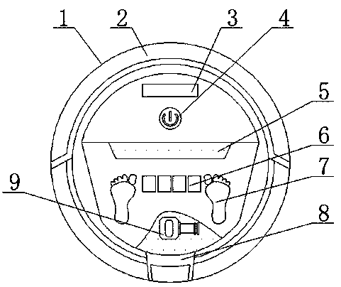
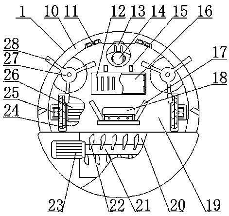
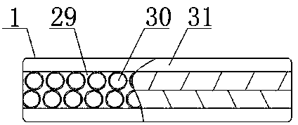
[0021] See Figure 1-4 , The present invention provides a technical solution: an impact-resistant cleaning robot, including a cleaning robot 1, a pressure sensor 9, a chassis 10, a drive motor 26, an elastic sleeve 31 and a damping pad 32, and an outer frame is provided on the outside of the cleaning robot 1 2. A nameplate 3 is arranged on the top of the upper surface of the cleaning robot 1, a start switch 4 is arranged under the nameplate 3, an indicator light 5 is arranged under the start switch 4, and a display screen 6 and a display screen 6 are arranged under the indicator lamp 5 A weighing area 7 is provided on the right side of the weighing area 7, a lifting handle 8 is provided below the weighing area 7, a pressure sensor 9 is installed inside the cleaning robot 1 on the side close to the upper surface, and the chassis 10 is installed on the lower surface of the cleaning robot 1. , And the chassis 10 is provided with a dust-proof cover 19, the top of the dust-proof cover 19 is provided with a distance sensor 11, and a universal wheel 13 is provided on the lower right side of the distance sensor 11. There is a universal wheel 14, and a charging patch 15 is provided under the universal wheel 13, a battery slot 16 is provided under the charging patch 15, a battery cover 12 is provided on the battery slot 16, and the battery slot 16 is provided below There is a vacuum cleaning port 18, a dust detector 17 is provided on the vacuum cleaning port 18, and a wheel 27 is provided on the upper left side of the vacuum cleaning port 18, a dusting brush 28 is provided on the wheel 27, and a driving motor 26 Installed inside the cleaning robot 1 near the lower surface, and the output end of the drive motor 26 is provided with a drive shaft 25, a drive wheel 24 is provided on the drive shaft 25, and a roller brush motor 23 is provided under the drive wheel 24. The output end of the motor 23 is provided with a rotating shaft 21, the rotating shaft 21 is provided with a rolling brush 22, and the side of the rolling brush 22 close to the upper surface is provided with an ash storage tank 20, the elastic sleeve 31 is installed on the outer frame 2, and the elastic sleeve 31 A ball storage ring 29 is arranged inside the ball storage ring 29, an elastic ball 30 is arranged inside the ball storage ring 29, a damping pad 32 is installed on the right side of the elastic ball 30, a spring 33 is arranged on the right side of the damping pad 32, a cleaning robot 1, an indicator light 5 , The display screen 6, the pressure sensor 9, the distance sensor 11, the dust detector 17, the roller brush motor 23 and the drive motor 26 are all electrically connected to the start switch 4.
[0022] In order to enable the user to measure the weight of the user through the cleaning robot 1, in this embodiment, preferably, the weighing zone 7 measures the weight of the weighed person through the pressure sensor 9, and the measurement result is displayed on the display screen 6.
[0023] In order to enable the cleaning robot 1 to obtain sufficient power, in this embodiment, preferably, two driving wheels 24 are provided, and the two driving wheels 24 are both installed on the lower surface of the cleaning robot 1.
[0024] In order to enable the driving wheel 24 to rotate better, in this embodiment, preferably, the driving wheel 24 and the driving motor 26 are rotatably connected through the driving shaft 25, and the driving wheel 24 drives the universal wheel 14 to rotate to control the cleaning robot 1 move.
[0025] In order to enable the roller brush 22 to better clean the dust on the ground, in this embodiment, preferably, the roller brush 22 and the roller brush motor 23 are rotatably connected through the rotating shaft 21, and the dust cleaned by the roller brush 22 is vacuumed. The port 18 is adsorbed and stored in the ash storage tank 20.
[0026] In order to enable the elastic sleeve 31 to reduce the wear of the cleaning robot 1 after a collision, in this embodiment, preferably, two elastic sleeves 31 are provided, and the two elastic sleeves 31 are both installed on the outer frame 2, and the elastic sleeve The bouncing ball 30 inside 31 will impact the spring 33 after the cleaning robot 1 collides with a hard object.
[0027] In order to enable the dusting brush 28 to gather the dust on both sides of the cleaning circuit on the inside of the chassis 10 of the cleaning robot 1, so that the roller brush 22 can collect the dust. In this embodiment, preferably, there are two dusting brushes 28. , And two dust-removing brushes 28 are installed on the lower surface of the cleaning robot 1. The dust-removing brush 28 can disperse dirt on the ground, so that the roller brush 22 can clean the dust.
[0028] In order to enable the distance sensor 11 to move according to a set route, in this embodiment, preferably, there are two distance sensors 11 in total, and the two distance sensors 11 are both installed on the lower surface of the cleaning robot 1.
[0029] In order to enable the cleaning robot 1 to withstand the impact caused by the impact and reduce the damage to the cleaning robot 1 caused by the impact, in this embodiment, preferably, the cleaning robot 1 and the outer frame 2 are fixedly connected by bolts, and the inside of the outer frame 2 A plurality of elastic balls 30 are provided on the ball storage ring 29.
[0030] The distance sensor in the present invention converts the mechanical displacement into a resistance or voltage output in a linear or arbitrary function relationship with the potentiometer element. The displacement of the object causes the resistance of the moving end of the distance sensor to change, and the change in resistance value reflects the displacement The increase or decrease of the resistance value indicates the direction of displacement. Usually, the power supply voltage is applied to the distance sensor to convert the resistance change into a voltage output.
[0031] The working principle and application process of the present invention: After the present invention is installed, the start switch 4 is turned on, the cleaning robot 1 cleans on a preset route, the cleaning robot 1 detects the path through the distance sensor 11, and the drive motor 36 passes through the drive shaft 25 Drive the driving wheel 24 to rotate to provide the power required for the movement of the cleaning robot 1. The driving wheel 24 cooperates with the universal wheel 14 to complete the movement of the cleaning robot 1, and the ash-raising brush 28 collects dust and dirt on the cleaning path when the cleaning robot 1 moves. Under the chassis 10, the rolling brush motor drives the rolling brush 22 to rotate through the rotating shaft 21 to clean dust and dirt. The cleaned dust is collected inside the ash storage tank 20 through the vacuum suction port 18. When the cleaning robot 1 is moving, it is received In an external impact, the elastic sleeve 31 on the outer frame 2 initially buffers the impact force brought about by the impact. The impact force after the buffering drives the elastic ball 30 to move in the ball storage ring 29, and most of the impact force is transmitted to the outside world. The impact force is eliminated under the contraction of the damping pad 32 and the spring 33, which reduces the impact of the impact on the cleaning robot 1, improves the operation stability of the cleaning robot 1, and increases the service life of the cleaning robot 1. The user stands in the weighing area The weight can be measured by the pressure sensor 9 on the 7 and the measured value is displayed on the display 6. After use, turn off the start switch 4, clean the dust in the ash storage tank 20, and use the charging patch 15 to control the battery tank 16 The battery inside is charged.
[0032] Although the embodiments of the present invention have been shown and described, those of ordinary skill in the art can understand that various changes, modifications, and substitutions can be made to these embodiments without departing from the principle and spirit of the present invention. And variations, the scope of the present invention is defined by the appended claims and their equivalents.

PUM

no PUM

Description & Claims & Application Information

We can also present the details of the Description, Claims and Application information to help users get a comprehensive understanding of the technical details of the patent, such as background art, summary of invention, brief description of drawings, description of embodiments, and other original content. On the other hand, users can also determine the specific scope of protection of the technology through the list of claims; as well as understand the changes in the life cycle of the technology with the presentation of the patent timeline. Login to view more.

Similar technology patents

Backpack type fruit tree trimming device

InactiveCN108668679AScientific and reasonable structureSafe to useCuttersMotor driven pruning sawsFruit tree pruningFruit tree
Owner:DENGFENG LAOSHUANBAO FERTILIZER CO LTD

Classification and recommendation of technical efficacy words

  • Scientific and reasonable structure
  • Safe to use

Stretchable nonwoven fabric and tape

ActiveUS20100035500A1High stretchabilitySafe to useAdhesive dressingsFibre disintegrationThermal shrinkageNonwoven fabric
Owner:KURARAY CO LTD

Endoscope light source device

InactiveUS20090203966A1Safe to useSufficient qualitySurgeryEndoscopesLight sourceEndoscope
Owner:FUJIFILM CORP
Why Eureka
Try Eureka