
Pull assistance device for varicosity stripping
A technique of pulling aids and varicose veins, applied in medical science, surgery, etc., can solve the problems of difficulty in grasping and operating, tight guide wire, low efficiency, etc., so as to reduce pain, bleeding time, and reduce trauma. Surface, easy installation and replacement effect
- Summary
- Abstract
- Description
- Claims
- Application Information
AI Technical Summary
Problems solved by technology
Method used
Image

Examples
Embodiment 1
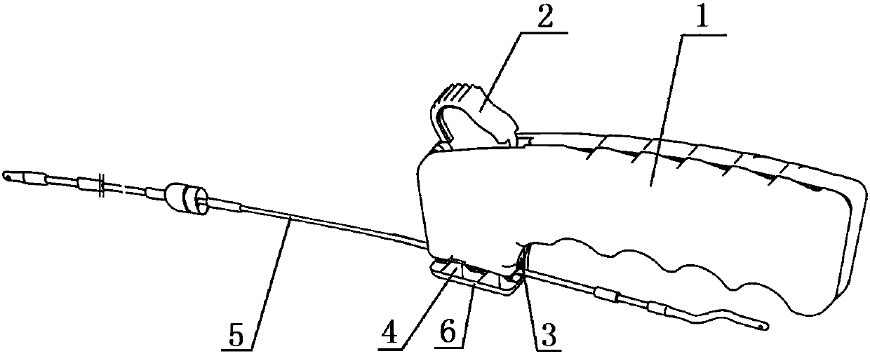
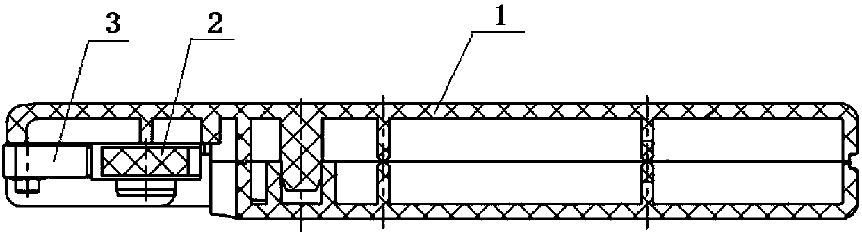
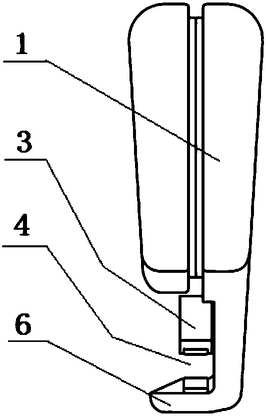
[0038] Embodiment 1: as attached figure 1 , 2 As shown in and 3, there is a cavity in the front upper part of the handle 1 as the machine compartment 102, the upper end of the machine compartment 102 is open, the upper end of the puller 2 protrudes from the opening, the lower part of the puller 2 is connected with the wire pressing block 3 through a transmission mechanism, and the handle 1 The lower part of the front end is longitudinally provided with a wire clamping groove 4, and a pressure bearing block 6 is fixed along the lower wire clamping groove 4. The bottom surface of the wire pressing block 3 is on the upper part of the wire clamping groove 4, and the wire pressing block 3 has pressing teeth 303 on the bottom surface of the wire clamping block. 6 top surfaces have bearing teeth 601.
[0039] In the foregoing, the pin shaft 101 is fixedly installed horizontally on the upper part of the machine compartment 102, the lower end of the puller 2 is connected to the cam 7,...
Embodiment 2
[0046] Embodiment 2: as attached Figure 7 As shown, the pin shaft 101 is fixedly installed horizontally on the upper part of the machine compartment 102, the cam 7 is installed on the pin shaft 101, and the lower part of the cam 7 is connected to the wire pressing block 3 by transmission; the motor 8 and the battery 9 are installed inside the handle 1, and the motor 8 is connected to the cam 7 shaft , The puller 2 is connected to the motor 8 and the battery 9 through a circuit. A bite force sensor 10 is installed on the top surface of the pressure block 6 or the bottom surface of the wire pressing block 3 . Wherein, the battery 9 is a rechargeable battery, or the battery 9 is replaced by an external power supply.
Embodiment 3
[0047] Embodiment 3: as attached Figure 8 As shown, the lower part of the machine compartment 102 is horizontally fixed with a sliding nail 107, and the corresponding position on the pressing block 3 is vertically provided with a lifting groove 305, and the fixing sliding nail 107 is inserted into the lifting groove 305 to slide. The wire pressing block 3 moves up and down along the lifting groove 305 driven by the cam 7 .
PUM
 Abstract
Description
Claims
Application Information