Automatic coiling and uncoiling device for distribution circuit power cable

A power cable, automatic retractable technology, applied in the direction of transportation and packaging, delivery of filamentous materials, thin material processing, etc., can solve the problems of manual retraction of power cables, uneven cable arrangement, etc., to achieve balance of gravity and avoidance If the force is too large, the effect of ensuring the winding strength and tightness

Active Publication Date: 2018-01-16
STATE GRID HENAN ELECTRIC ZHOUKOU POWER SUPPLY +1
View PDF11 Cites 34 Cited by
  • Summary
  • Abstract
  • Description
  • Claims
  • Application Information

AI Technical Summary

Problems solved by technology

[0006] In view of this, the object of the present invention is to address the deficiencies of the prior art, to provide an automatic retractable device for power cables of distribution lines, which solves the problems that existing power cables need to be manually retracted and the cables are arranged unevenly during retraction.

Method used


Image

  • Automatic coiling and uncoiling device for distribution circuit power cable
  • Automatic coiling and uncoiling device for distribution circuit power cable
  • Automatic coiling and uncoiling device for distribution circuit power cable

Examples


Embodiment 1

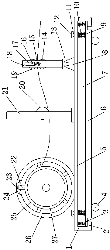
[0029] Such as figure 1 As shown, the power cable automatic retracting device for distribution lines includes a base 5, a cavity I7 is provided at the bottom of the base 5, a sliding plate 6 is provided in the cavity I7, and limit protrusions 3 are provided at both ends of the sliding plate 6, and the cavity The lower end of I7 is provided with a limit block 2 matching with the limit protrusion 3, universal rollers 4 are installed at the four corners of the lower end of the sliding plate 6, and a tension spring 1 is arranged between the sliding plate 6 and the top wall of the cavity I7. The sliding plate 6 is contracted upward by the tension spring 1, and the base 5 can be placed on the ground stably. The base 5 is provided with an ejection device for pushing the sliding plate 6 downward, and the sliding plate 6 is pushed downward by the ejection device. out, so that the universal roller 4 touches the ground, which facilitates the movement of the entire frame and is easy to use....

Embodiment 2

[0035] It differs from Embodiment 1 in that: as figure 1 As shown, the ejector device includes an adjustment rod 11 slidingly connected to the four corners of the base 5, the adjustment rod 11 extends into the cavity I7, the bottom of the adjustment rod 11 is fixedly connected with a support pad 9, and the support pad 9 leans against the sliding plate 6 On the upper end surface, the adjustment rod 11 is covered with a compression spring 10, and the two ends of the compression spring 10 are respectively abutted against the top wall of the cavity I7 and the upper end surface of the support plate 9, and the top of the adjustment rod 11 is connected with a handle 12. The rod 11 is fixed on the base 5 by a limit pin.

[0036] When the adjustment rod 11 is fixed on the base 5 through the limit pin, the sliding plate 6 is contracted upward by the tension spring 1, and the base 5 is placed on the ground stably; when the sliding plate 6 needs to be ejected downward, the limit pin is pu...

Embodiment 3

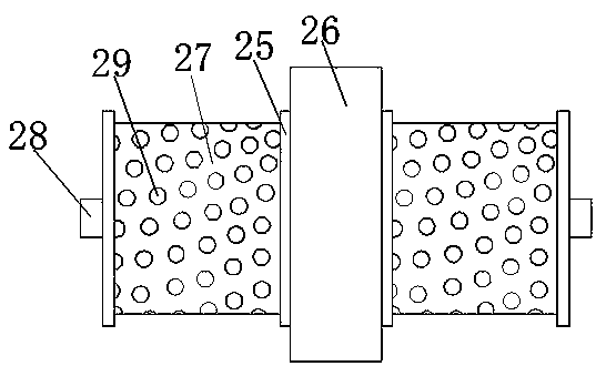
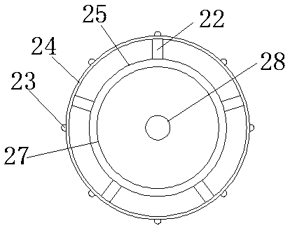
[0038] It differs from Embodiment 1 in that: as figure 2 As shown, the reel 27 is provided with a weight-reducing hole 29, which can reduce the weight of the reel, facilitate the movement and portability of the entire frame, and accelerate the retracting and unwinding of the cables.


PUM


Abstract

The invention discloses an automatic coiling and uncoiling device for a distribution circuit power cable. The automatic coiling and uncoiling device comprises a base, wherein a chamber I is arranged at the bottom of the base; a sliding plate is arranged in the chamber I; universal idler wheels are arranged at four corners at the lower end of the sliding plate; an extension spring is arranged between the sliding plate and the top wall of the chamber I; a jacking device is arranged on the base; a coiling device, a tensioning device and a cable uncoiling device are arranged on the base in turn; the coiling device comprises an outer support ring and an inner support ring; a rolling structure is arranged between the outer support ring and the inner support ring; a rotating ring is fixedly connected with the middle part of the inner support ring; coiling plates are respectively arranged at the two ends of the rotating ring; the tensioning device comprises a tensioning bracket and a tensioning roller; the two ends of the tensioning roller are arranged on the tensioning bracket; and the cable uncoiling device comprises an uncoiling mechanism capable of reciprocating and an uncoiling driving motor connected with the uncoiling mechanism. According to the invention, the coiling device, the tensioning device and the cable uncoiling device are successively arranged, so that the automatic coiling and uncoiling of the cable can be realized and the winding intensity, tightness and uniformity of the cable can be guaranteed.

Description

technical field [0001] The invention belongs to the technical field of electric power construction, and in particular relates to an automatic retractable device for power cables of distribution lines. Background technique [0002] In the construction of the power industry, it is generally necessary to lower the entire cable and then install the cable. At present, the method of lowering the entire cable for construction is generally manual work. One of the lowering methods is: a rotating shaft is inserted into the center of the cable drum, and the rotating shaft is set horizontally. Both ends are supported by brackets, and then the cable drum is manually rotated. Cable lowering operation; another lowering method is to set the cable drum axially vertically and place it on a chassis that can be rotated horizontally. The cable lowering operation is still performed by manually rotating the cable drum. A positioning rod is vertically set in the center of the chassis, and the chass...

Claims


Application Information

Patent Timeline
Patent Type & Authority Applications(China)
IPC IPC(8): B65H75/44B65H59/10
Inventor 施学召张浩赵志健张洋
Owner STATE GRID HENAN ELECTRIC ZHOUKOU POWER SUPPLY
Why Eureka
Try Eureka