Liquid container

A liquid container and liquid technology, applied in the field of machinery, can solve the problems of waste of bottom space, puncture or damage of the inner bag, liquid leakage, etc., so as to avoid the waste of space and increase the filling volume.

Active Publication Date: 2018-01-16
TALOS TECH CORP
View PDF10 Cites 7 Cited by
  • Summary
  • Abstract
  • Description
  • Claims
  • Application Information

AI Technical Summary

Problems solved by technology

However, if the exhaust has a certain hardness, although the exhaust structure can maintain its original shape and extend to the middle or bottom of the outer barrel smoothly after inverting the entire liquid container, but when the inner bag is continuously filled with liquid and opened, it should have hardness. If the exhaust is too soft, it will be easily affected by gravity or the inner bag will be stretched when the liquid is poured upside down. During the process, it is folded or tilted due to the friction and extrusion of the inner bag, so that the exhaust structure is still accumulated on the neck of the outer barrel, and the gas at the bottom is still not discharged, and the bottom space that can store liquid is still wasted
Therefore, it is still impossible to effectively improve the filling capacity of the liquid container in the prior art.

Method used


Image

  • Liquid container
  • Liquid container
  • Liquid container

Examples


Embodiment 1

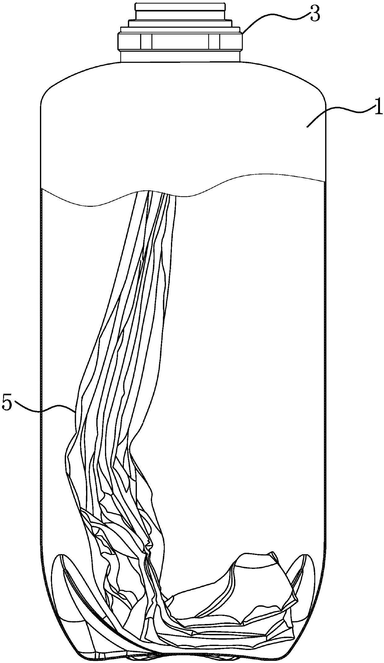
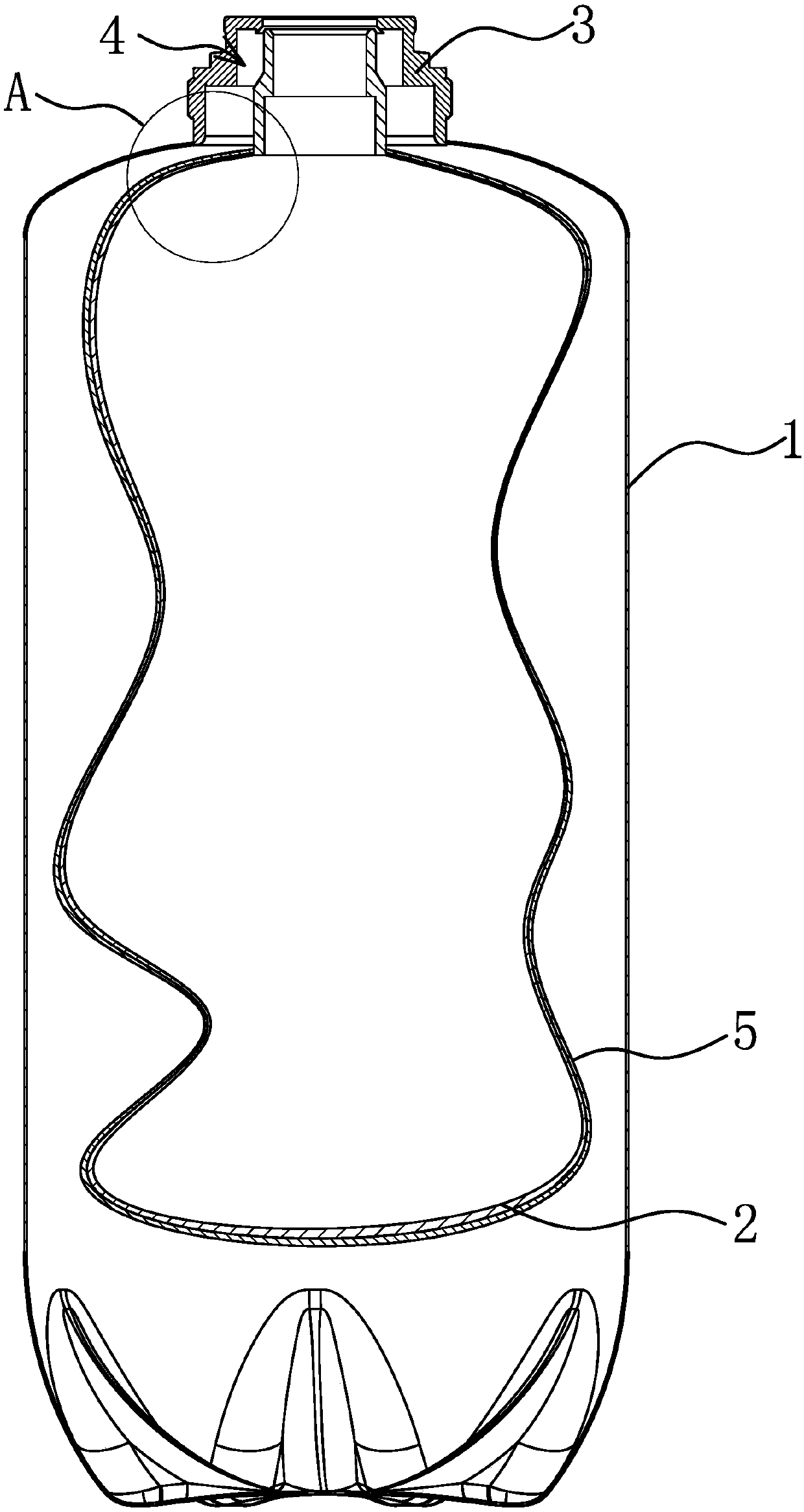
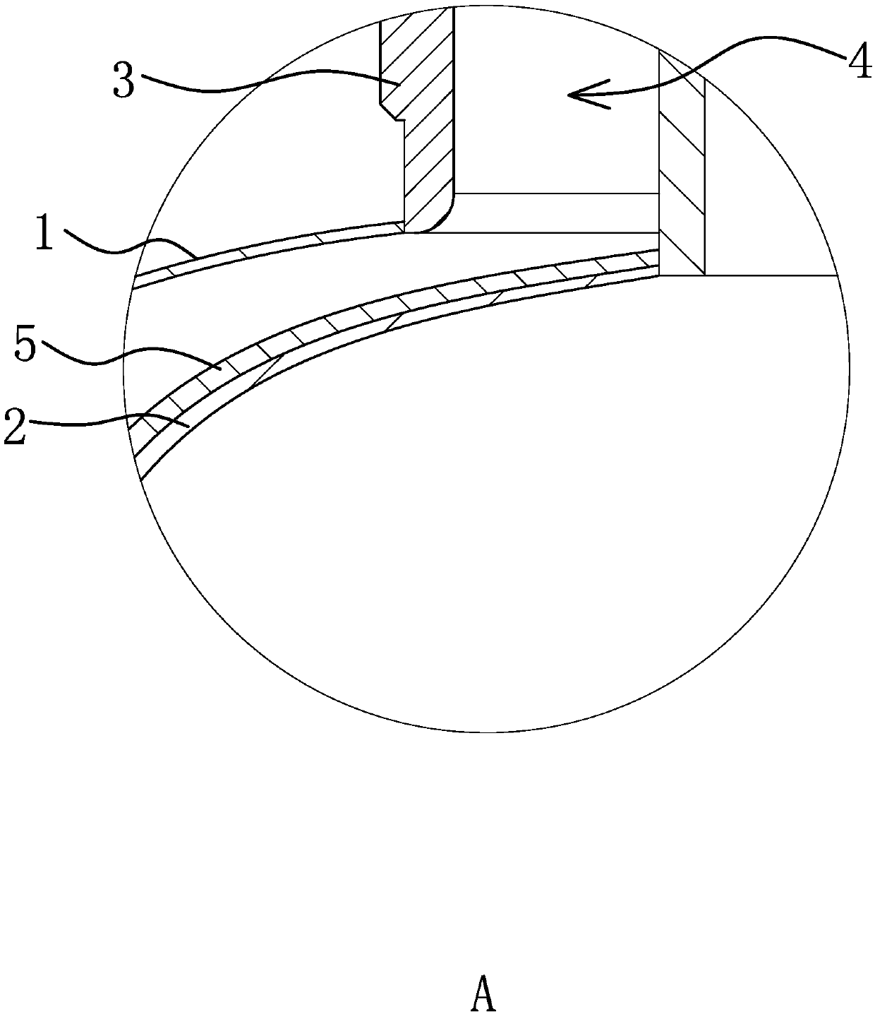
[0037] Such as Figure 1 to Figure 2 As shown, a liquid container includes a barrel-shaped outer shell 1, a flexible inner bag 2 arranged in the outer shell 1 for storing liquid, a liquid outlet valve 3 for controlling the liquid in and out of the inner bag 2, the inner bag 2 and the liquid outlet valve 3 is fixedly connected and the bag mouth of the inner bag 2 forms a seal with the liquid outlet valve 3, and the outer shell 1 forms a seal with the liquid outlet valve 3, and the end of the outer shell 1 connected with the liquid outlet valve 3 is also connected with a ventilator that can control the gas in and out of the outer shell 1 Structure 4, the ventilation structure 4 includes a ventilation channel 1 located on the liquid outlet valve 3 . Ventilation channel 1 can be directly provided on the liquid outlet valve 3, so that various liquid discharge structures and vent structures 4 are relatively compact.

[0038] Such as image 3 , Figure 4 As shown, a separation bag...

Embodiment 2

[0044] The structure and principle of this embodiment are basically the same as that of Embodiment 1, the difference is that: Figure 5 As shown, the shape of the protrusion 511 is a triangle, and the triangular protrusion 511 is also very convenient to process, easy to form, and the edges are relatively neat, which can ensure that the edges of the formed auxiliary air channel 1 52 and auxiliary air channel 2 512 are relatively smooth, ensuring The gas is discharged smoothly,

Embodiment 3

[0046] The structure and principle of this embodiment are basically the same as that of Embodiment 1, the difference is that: Figure 6 to Figure 8 As shown, the convex portion 51 includes elongated convex strips 513 , and at least one convex strip 513 extends from the opening of the partition bag 5 to the bottom of the partition bag 5 . The arrangement of the convex strips 513 can ensure that the formed auxiliary air channel-52 is smooth from the beginning to the end, and ensure the smooth discharge of gas, so as to increase the filling volume of the liquid container during filling. Moreover, the complete convex strip 513 is easy to process and convenient to form. Specifically, the protruding strips 513 are wrinkled and formed by bonding the inner surfaces of the separation bag 5, that is, the inner surfaces of the separation bag 5 are partially pasted to form a wrinkled protrusion 511, and the protrusions 511 can be multiple Continuous pleats are superimposed to further enh...


PUM


Abstract

The invention provides a liquid container and belongs to the technical field of machinery. The problem of low filling volume of an existing liquid container is solved. The liquid container which is ofan improved structure comprises a bucket-shaped shell, a flexible inner bag which is arranged in the shell and used for storing liquid and a liquid outlet valve which controls flow-in and flow-out ofliquid in the inner bag, the inner bag is fixedly connected with the liquid outlet valve, a bag opening of the inner bag and the liquid outlet valve form seal, and the shell and the liquid outlet valve form seal; one end of the liquid outlet valve is connected to the shell, a ventilation structure which can control gas to enter and leave from the shell is further connected to the shell, and a separation bag is further arranged between the inner bag and the shell in a sleeving mode; the separation bag is a flexible bag, a plurality of protrusion portions which protrude out of the surface of the separation bag are arranged on the separation bag, each protrusion portion extends in the direction away from the bag opening of the separation bag from the bag opening of the separation bag, a first auxiliary air channel which is used for air circulation is formed between two adjacent protrusion portions, and the first auxiliary air channel can always be communicated with the ventilation structure. The filling volume of the liquid container which is of an improved structure is greatly improved.

Description

technical field [0001] The invention belongs to the technical field of machinery, and relates to a container, in particular to a liquid container. Background technique [0002] There are many kinds of liquid containers on the market, such as a wine barrel, which is a tool for holding wine. Generally, there is a wine spear at the mouth of the barrel, and the wine spear cooperates with the dispenser to realize the wine barrel Squeeze out the alcohol inside. At present, the barrels commonly used in the market are hard metal barrels. The hard metal wine barrel can resist the high pressure generated by the internal gas and provide enough strength to ensure that it will not be burst. However, this kind of metal wine barrel is costly and troublesome to clean. Generally, merchants do not have special equipment for cleaning metal wine barrels. Therefore, after the wine in the barrel is used up, the empty barrel needs to be transported to the manufacturer for cleaning. , thus incre...

Claims


Application Information

Patent Timeline
IPC IPC(8): B67D1/04B67D1/08
CPCB65D77/06B65D2205/00B65D85/72B67D1/0001B67D1/0412B67D1/0462B67D1/06B67D1/1279
Inventor 邱迪林
Owner TALOS TECH CORP
Why Eureka
Try Eureka