FCDI device for enhancing trace ion trapping, based on ion exchange resin, and application thereof

A technology of ion exchange resin and ions, which is applied in the direction of separation methods, dispersed particle separation, chemical instruments and methods, etc., can solve the problems of local current higher than the limit current, low electrosorption efficiency, ion exchange membrane scaling, etc., to achieve Good electrical adsorption adaptability, fast capture ability, and the effect of solving the concentration polarization phenomenon

Active Publication Date: 2018-01-16
NORTHEASTERN UNIV
View PDF2 Cites 11 Cited by
  • Summary
  • Abstract
  • Description
  • Claims
  • Application Information

AI Technical Summary

Problems solved by technology

[0006] However, there are still some deficiencies in FCDI technology at present: although the applied electric field is lower than the electrolysis voltage of water, there is a phenomenon that the local current inside the electrode chamber is higher than the limiting current. Causes a weak concentration polarization effect, which leads to a decrease in efficiency
During the long-term operation of the reactor, the concentration difference of calcium and magnesium ions in the influent may even cause scaling of the ion exchange membrane in some cases. These phenomena are one of the factors that cause the low efficiency of FCDI technology.

Method used


Image

  • FCDI device for enhancing trace ion trapping, based on ion exchange resin, and application thereof
  • FCDI device for enhancing trace ion trapping, based on ion exchange resin, and application thereof
  • FCDI device for enhancing trace ion trapping, based on ion exchange resin, and application thereof

Examples


Embodiment 1

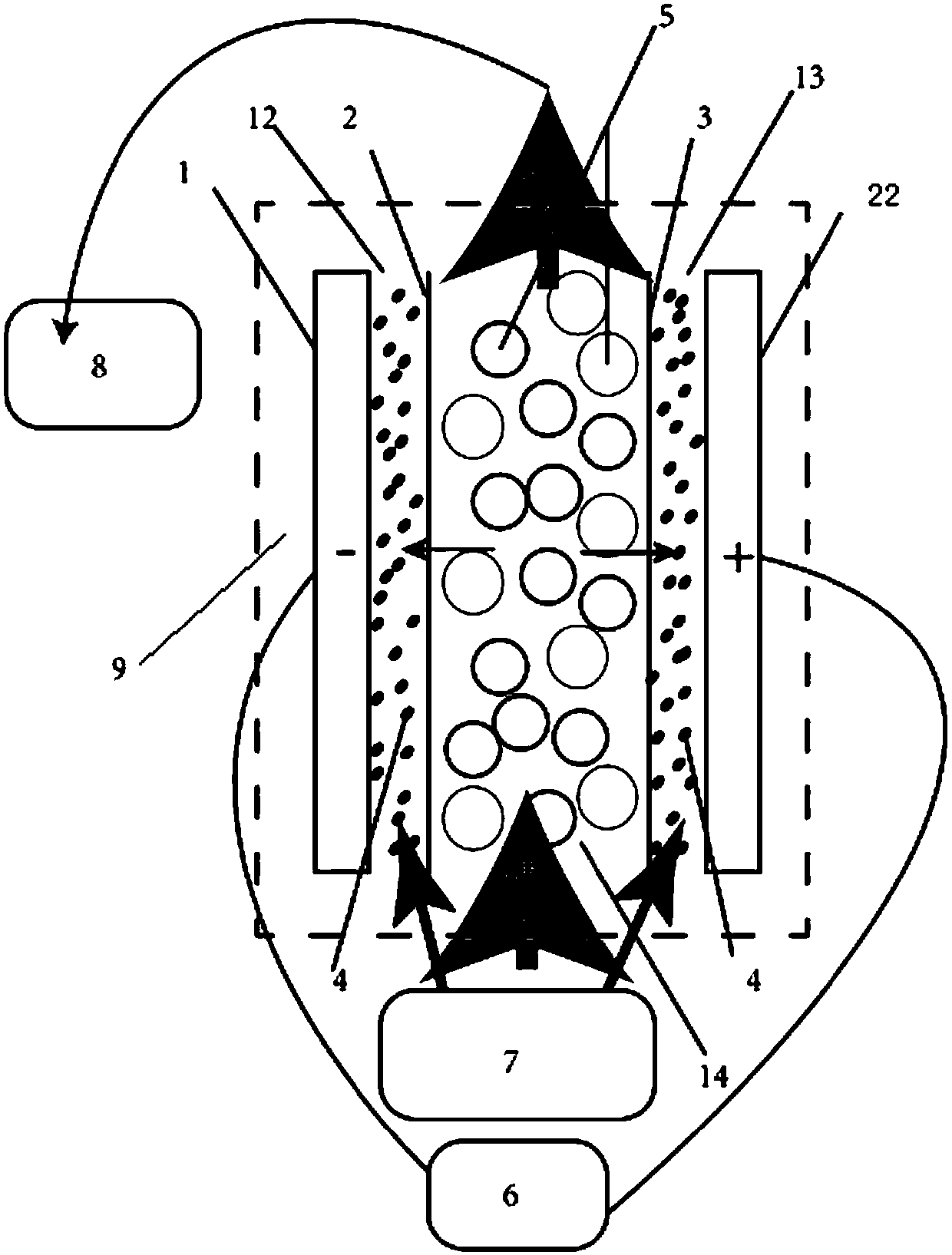
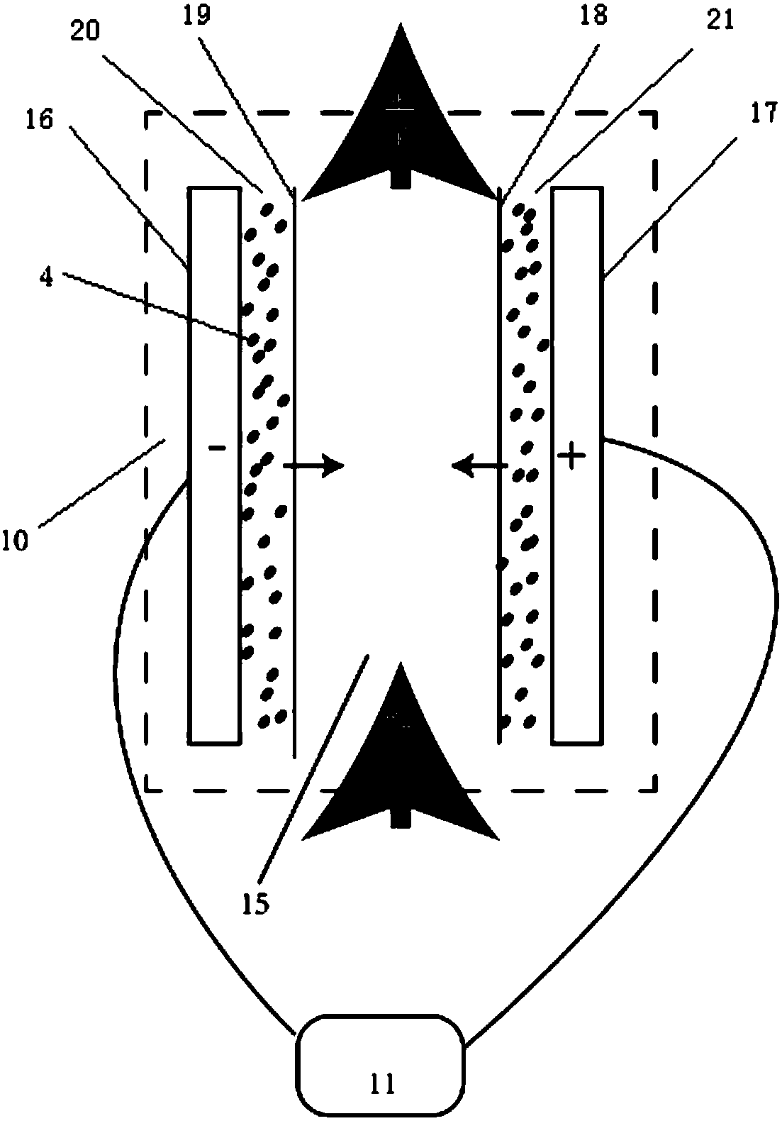
[0045] Anion-exchange membrane one 3, cation-exchange membrane one 2, anion-exchange membrane two 18, and cation-exchange membrane two 19 were soaked in 0.1mol / L potassium hydroxide solution and 0.1mol / L sulfuric acid solution for 24 hours before use, and after taking out Rinse several times with deionized water.

[0046] Before use, the ion exchange resin bed was soaked in 0.1mol / L potassium hydroxide solution and 0.1mol / L sulfuric acid solution for 24 hours, rinsed with deionized water several times after taking it out, and then dried in a vacuum oven at 60°C Dry.

[0047] Follow the steps below:

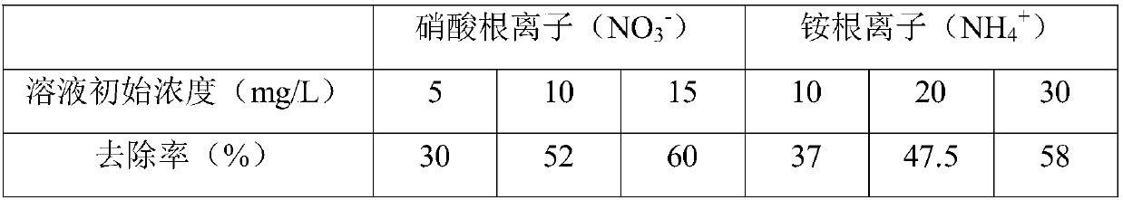
[0048] (1) Use deionized water (conductivity less than 5μs / cm) to prepare NaNO with initial concentrations of 5mg / L, 10mg / L and 15mg / L respectively 3 The solution simulates raw water.

[0049] (2) The fluid electrode 4 adopts the mode of circulating in and out, and the fluid electrode 4 is extracted from the beaker by using a dual-channel peristaltic pump, and enters from the b...

Embodiment 2

[0055] The difference from Example 1 is that deionized water (conductivity less than 5 μs / cm) is used to prepare NH with initial concentrations of 10 mg / L, 20 mg / L and 30 mg / L 4 Cl solution was used to simulate raw water; the removal rate of ammonium ions was calculated, and the results are shown in Table 1.

[0056] Table 1 Effect of ion exchange resin bed FCDI on low concentration NO 3 - and NH 4 + The removal rate

[0057]


PUM


Abstract

The invention relates to an FCDI device for enhancing trace ion trapping, based on ion exchange resin, and the application thereof. The FCDI device adopts the technical scheme that the FCDI device comprises an electric adsorption module unit, an electric desorption ion recycling module unit, fluid electrode, a fluid electrode conveying unit, a voltage supply unit, a diluting compartment and a concentrating compartment, the electric adsorption module unit is positioned in the diluting compartment; the electric desorption ion recycling module unit is positioned in the concentrating compartment;the electric adsorption module unit comprises an ion exchange resin bed, a cathode graphite collector plate I, an anode graphite collector plate II, an anion exchange membrane I, a cation exchange membrane I, a cathode electrode chamber I and an anode electrode chamber I. By adding the ion exchange resin bed in the electric adsorption module unit, the FCDI device optimizes the process of deionization performed on low-concentration inlet water by an FCDI system, weakens the concentration polarization effect, and enhances the electricity removal rate.

Description

technical field [0001] The invention belongs to the technical field of environmental engineering and water treatment, and in particular relates to an ion exchange resin-based enhanced trace ion trapping FCDI device and its application. Background technique [0002] An electro-adsorption desalination technology derived from electrochemical principles, also known as capacitive deionization technology (CDI), has the ability to avoid the problems of the above desalination technologies because of its simplicity, low energy consumption, and environmental friendliness. more and more people's attention and attention. The basic principle of this technology is that by applying an external voltage to the porous adsorption electrode, an electrostatic field is formed between the two electrodes, and the charged ions are forced to move to the electrode with the opposite charge under the action of the electrostatic field. The negative and positive ions in the solution move to the positive ...

Claims


Application Information

Patent Timeline
Patent Type & Authority Applications(China)
IPC IPC(8): C02F1/469C02F101/12C02F101/16
Inventor 赵研王军郎朗胡筱敏
Owner NORTHEASTERN UNIV
Why Eureka
Try Eureka