Eureka AIR delivers breakthrough ideas for toughest innovation challenges, trusted by R&D personnel around the world.

Isolation type high potential electricity-taking method

A high-potential, electrical method technology, applied in the direction of voltage/current isolation, satellite radio beacon positioning system, measuring electricity, etc., can solve the problems of increasing external line laying, difficult power-taking operation, power-taking device isolation, etc., to achieve Achieve automatic management and monitoring, reduce manual operations, and achieve precise positioning effects

Inactive Publication Date: 2018-01-16
河南汇纳科技有限公司
View PDF7 Cites 0 Cited by
  • Summary
  • Abstract
  • Description
  • Claims
  • Application Information

AI Technical Summary

Problems solved by technology

[0003] However, most of the current power-taking devices adopt the method of introducing control signal lines to realize the transmission of control information, which cannot effectively isolate the power-taking devices, and it is difficult to ensure power-taking operations in a closed environment, and The introduction of control signal lines increases the laying of external lines in the high-voltage transmission line network, which can easily cause circuit accidents, damage the power supply system, and cause electrical safety accidents such as leakage accidents.

Method used


Image

  • Isolation type high potential electricity-taking method
  • Isolation type high potential electricity-taking method
  • Isolation type high potential electricity-taking method

Examples


Embodiment Construction

[0026] The following will clearly and completely describe the technical solutions in the embodiments of the present invention with reference to the accompanying drawings in the embodiments of the present invention. Obviously, the described embodiments are only some, not all, embodiments of the present invention. Based on the embodiments of the present invention, all other embodiments obtained by persons of ordinary skill in the art without making creative efforts belong to the protection scope of the present invention.

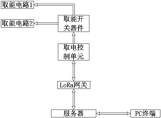
[0027] Such as Figure 1-3 As shown, an isolated high potential power-taking method is characterized in that it comprises the following steps:

[0028] Step 1, input the power fetching command according to the demand;

[0029] Step 2, analyze the power fetching command in step 1;

[0030] Step 3, sending the communication information analyzed in Step 2 to the power-taking control unit through the wireless network;

[0031] Step 4, selectively extract power ...


PUM


Abstract

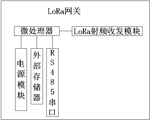
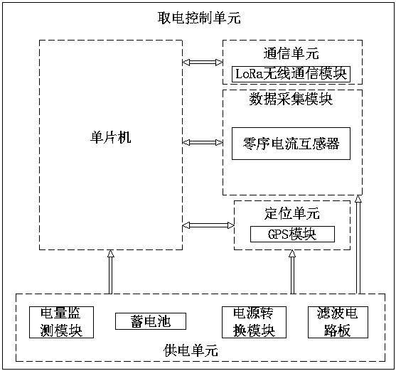
The invention discloses an isolation type high potential electricity-taking method. The isolation type high potential electricity-taking method comprises steps of inputting an electric-taking order according to a demand, 2, performing analysis on the electricity-taking order, 3, transmitting communication information obtained through analysis to an electricity-taking control unit, and 4, performing selective electricity-taking according to communication information received by the electricity-taking control unit. In order to realize the isolation type high potential electricity-taking method,the invention provides an electricity-taking system for realizing the method. The isolation type high potential electricity-taking system comprises a PC terminal for inputting an electricity-taking order and a server. The server is connected to an LoRa gateway for performing analysis on the electricity-taking order. The LoRa gateway is connected to the electricity-taking control unit which is usedfor receiving and executing the electricity-taking order. The electricity-taking cotnrol unit is connected to an energy-taking switch device for executing the electricity-taking order. The energy-taking switch is selectively connected to at least two paths of energy-taking paths in order to realize selective electricity-taking. The isolation type high potential electricity-taking method realizeslong distance electricity-taking, saves energy, has a good isolation effect and can accurately position.

Description

technical field [0001] The invention belongs to the technical field of high-potential electricity extraction, and in particular relates to an isolated high-potential electricity extraction method. Background technique [0002] In order to realize the normal power supply of high-voltage overhead transmission lines or transformers, some testing equipment is usually installed on high-voltage overhead transmission lines or transformers, and these devices are independent of high-voltage overhead transmission lines or transformers, and their power supply methods are mostly powered by batteries However, the power stored in the battery is limited. In order to make the detection equipment run for a long time, maintenance personnel are usually required to replace the battery. This undoubtedly increases the workload of the electrical industry and has potential personal safety hazards. In order to prevent maintenance personnel from performing power maintenance work near high-voltage tra...

Claims


Application Information

Patent Timeline
Patent Type & Authority Applications(China)
IPC IPC(8): G01R31/08G01R19/25G01R15/18G01R31/36G01S19/14G05B19/042H04L29/08
Inventor 马清詹望
Owner 河南汇纳科技有限公司
Why Eureka
Eureka Blog
Learn More