Radio frequency tag testing device based on FPGA

A technology of radio frequency tags and testing devices, which is applied in the field of integrated circuit verification testing, can solve the problems of increasing chip test circuit logic, increasing chip area, etc., and achieve the effect of reducing test circuit functions, reducing chip area, and improving processing capabilities

Inactive Publication Date: 2018-01-16
华大恒芯科技有限公司
View PDF2 Cites 5 Cited by
  • Summary
  • Abstract
  • Description
  • Claims
  • Application Information

AI Technical Summary

Problems solved by technology

Due to the limitation of the performance of the test equipment, it is often necessary to complete some functions in the chip under test, whi

Method used


Image

  • Radio frequency tag testing device based on FPGA
  • Radio frequency tag testing device based on FPGA
  • Radio frequency tag testing device based on FPGA

Examples


Example Embodiment

[0026] Specific embodiments of the present invention will be described below in conjunction with the accompanying drawings.

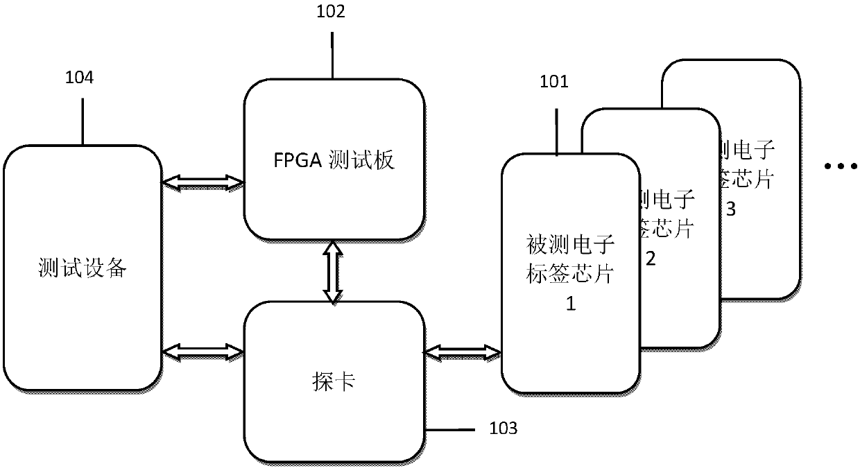
[0027] like figure 1 As shown, the present invention provides a kind of FPGA-based radio frequency label test device for testing radio frequency label chip 101, is made up of FPGA test board 102 and probe card 103; Wherein,

[0028] The electronic label chip 101 is used to receive the test command sent by the FPGA test board 102. The test command format includes command code and command data. The command code is, for example, an 8-bit code composed of symbols 0 and 1. Other formats are also conceivable. The command code is sent first, and the command data is sent later, which is convenient for the electronic label chip 101 to decode. After the electronic label chip 101 is decoded, the test operation is performed, and the test state is output after the test is completed, for sampling by the FPGA test board 102;

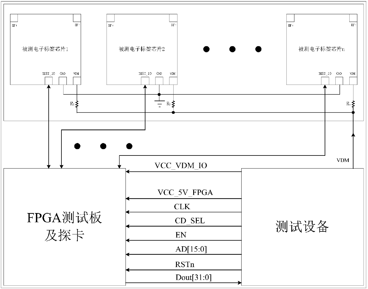
[0029] The FPGA test board 102 is used ...


PUM


Abstract

The invention provides a radio frequency tag testing device based on an FPGA, and the device comprises an FPGA test board and a probe card. An electronic tag chip is used for receiving a test commandtransmitted by the FPGA test board, executing the testing operation after decoding, and outputting a testing state after testing so that the FPGA test board carries out the sampling. The FPGA test board receives the test command transmitted by test equipment, completes the command decoding and data coding and transmits the data to the electronic tag chip, and also receives the testing state afterthe testing of the electronic tag chip, and transmits the testing state to the test equipment. The probe card is an electric contact interface of a tested electronic tag chip and the test equipment. The test equipment transmits the test command and data to the FPGA test boar, and determines whether the function of the electronic tag chip is correct or not according to the output testing state of the FPGA test board. The invention also provides a radio frequency tag testing method based on the FPGA.

Description

technical field [0001] The invention relates to the field of verification testing of integrated circuits, in particular to a device for testing radio frequency electronic tags. Background technique [0002] The screening test is an important link to ensure the quality and reliability of the chip. Taking the radio frequency tag chip as an example, the screening test has completed functions such as chip clock calibration (trimming), functional test, burn-in test, and initialization settings. It is highly automated and fully covered by samples. It is currently the most efficient product inspection method to realize the functions of product pre-inspection and application initialization. [0003] In order to realize the screening test function, a certain test circuit needs to be added in the chip design, so as to cooperate with the test equipment to realize various test items, and the execution time of these test items is also directly related to the test technical solution. For...

Claims


Application Information

Patent Timeline
IPC IPC(8): G01R31/28
Inventor 包玉华徐海军廖峰卢菊春龚永鑫
Owner 华大恒芯科技有限公司
Why Eureka
Try Eureka