Valve clamping device

A technology for valves and clamping teeth, applied in the direction of heart valves, etc., can solve problems such as difficulty in increasing the clamping force, taking a long time, and difficulty in capturing valves

Active Publication Date: 2018-01-19
SHANGHAI HANYU MEDICAL TECH CO LTD
View PDF5 Cites 12 Cited by
  • Summary
  • Abstract
  • Description
  • Claims
  • Application Information

AI Technical Summary

Problems solved by technology

However, it contains a complex control system, and the cost of manufacturing and production is also very high; the device needs to go through the vein, right atrium, atrial septum, and left atrium to reach the left ventricle during the operation, and the approach is long and has many bends. The surgical operation is very complicated. The doctor needs to repeatedly fine-tune the curvature, direction, horizontal position, and vertical depth of the delivery system, and the valve can only be clamped after reaching the ideal position. There

Method used


Image

  • Valve clamping device
  • Valve clamping device
  • Valve clamping device

Examples


Embodiment Construction

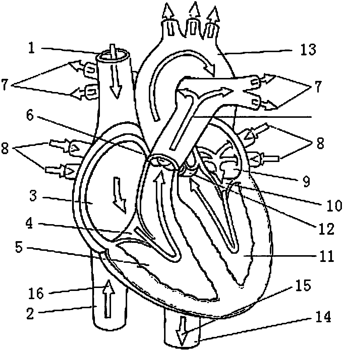
[0043] This embodiment provides an improved valve clamp for treating mitral valve regurgitation, the valve clamp has a separate first clamping part 30, a second clamping part 40 and a The fixing part 50 detachably fixes the first clamping part 30 and the second clamping part 40 . Wherein, the first clamping arm 301 and the second clamping arm respectively provided on the first clamping part 30 and the second clamping part 40 can form a pair of clamps, which can be brought together by external force and squeeze the valve therein. , so as to achieve the purpose of clamping.

[0044] The purpose and effect of each component design in the present invention will be deeply understood through the detailed description of each functional component in this embodiment below.

[0045] The valve clamp in this embodiment uses the clamping arms that cooperate with each other on the clamping parts to clamp the valve. In order to improve the clamping ability of the clamping arms to the valve ...


PUM

PropertyMeasurementUnit
Lengthaaaaaaaaaa

Abstract

The invention discloses a valve clamping device. The valve clamping device comprises a first clamping component, a second clamping component and a fixing component. The fixing component is used for fixing the first clamping component and the second clamping component. The first clamping component comprises at least two first clamping arms. The second clamping component comprises a corresponding number of second clamping arms. A pair of clamps can be formed by each first clamping arm and the corresponding second clamping arm. The valve clamping device has the advantages that the valve clampingdevice can employ the smooth-transition top design, the high-clamping-stability clamping tooth design and the 'one-stripe-for-dualpurpose' fixing ring deign, so that damage to valves during movement of the clamping device is reduced, users capture the valves conveniently, and clamping performance is improved while damage to the valves is reduced; the overall structure of the clamping device has high machinability, and production and manufacture of factories are facilitated.

Description

technical field [0001] The invention relates to a valve clamp, in particular to a valve clamp for treating heart valve regurgitation. Background technique [0002] The mitral valve is a two-valve valve attached to the periphery of the left atrioventricular orifice (eg figure 1 As shown), it is connected to the papillary muscle by the chordae, which prevents the blood from the left ventricle from flowing back to the left atrium. [0003] Mitral regurgitation (MR) is due to the organic or functional changes in the mitral valve leaflets and their related structures, resulting in poor anastomosis of the anterior and posterior leaflets of the mitral valve, and blood flow back from the left ventricle to the left atrium, causing a series of pathological Physiological changes. Severe MR can cause left ventricular enlargement, and eventually lead to left ventricular systolic failure and heart failure. At the same time, left atrial pressure also increases due to reflux, which can ea...

Claims


Application Information

Patent Timeline
IPC IPC(8): A61F2/24
Inventor 戴宇峰杨惠仙罗鹏潘炳跃
Owner SHANGHAI HANYU MEDICAL TECH CO LTD
Why Eureka
Try Eureka