
Automatic grinding device for strain clamp parts

A technology of tension-resistant wire clamp and clamping device, which is applied in the direction of grinding/polishing safety device, control of workpiece feed movement, grinding machine, etc., and can solve the problem of small contact surface, poor insertion and wasteful clamping and connection on the clamp , slow speed and other problems, to achieve efficient and reliable grinding and cleaning, improve work efficiency, and ensure production safety.

Active Publication Date: 2018-01-19
徐州宇飞电力科技有限公司
View PDF7 Cites 3 Cited by
  • Summary
  • Abstract
  • Description
  • Claims
  • Application Information

AI Technical Summary

Problems solved by technology

[0002] At present, there are mainly three kinds of devices for fixing and clamping the steel-reinforced aluminum stranded wire in domestic transmission line connection clamps. One is wire plugging, the contact surface is small and the plugging is not strong, and the wires are prone to heat; the other is aluminum tube hydraulic pressure. When installing, the wires at both ends are inserted into the aluminum tube, and then pressurized with a hydraulic tool, but the contact surface is small and the grip is not strong; The impact force changes the metallographic phase, the mechanical strength is reduced, and the explosion is not safe
At present, due to the special structure of the wire clip, in order to facilitate the subsequent installation of the cast wire clip, it is necessary to grind the connection hole on the wire clip and the surrounding of the connection hole to facilitate subsequent tapping. Traditionally, the processing of the entire position is done by workers. Directly use the lathe for processing, first fix it and then use the lathe tool for processing. Although this method is more accurate, the speed is very slow. About 10 pieces can be processed in one hour, and the main time is wasted on clamping the connecting wire clamp. Therefore it is urgent to develop a fixture that can quickly process the connecting wire clamp

Method used


Image

  • Automatic grinding device for strain clamp parts

Examples


Embodiment Construction

[0010] In order to facilitate the understanding of the present invention, the present invention will be described more fully below with reference to the associated drawings. Several embodiments of the invention are shown in the drawings. However, the present invention can be embodied in many different forms and is not limited to the embodiments described herein. Rather, these embodiments are provided so that the disclosure of the present invention will be thorough and complete.

[0011] It should be noted that when an element is referred to as being “fixed on” another element, it may be directly on the other element or there may be an intervening element. When an element is referred to as being "connected to" another element, it can be directly connected to the other element or intervening elements may also be present. The terms "vertical," "horizontal," "left," "right," and similar expressions are used herein for purposes of illustration only.

[0012] Unless otherwise def...


PUM


Abstract

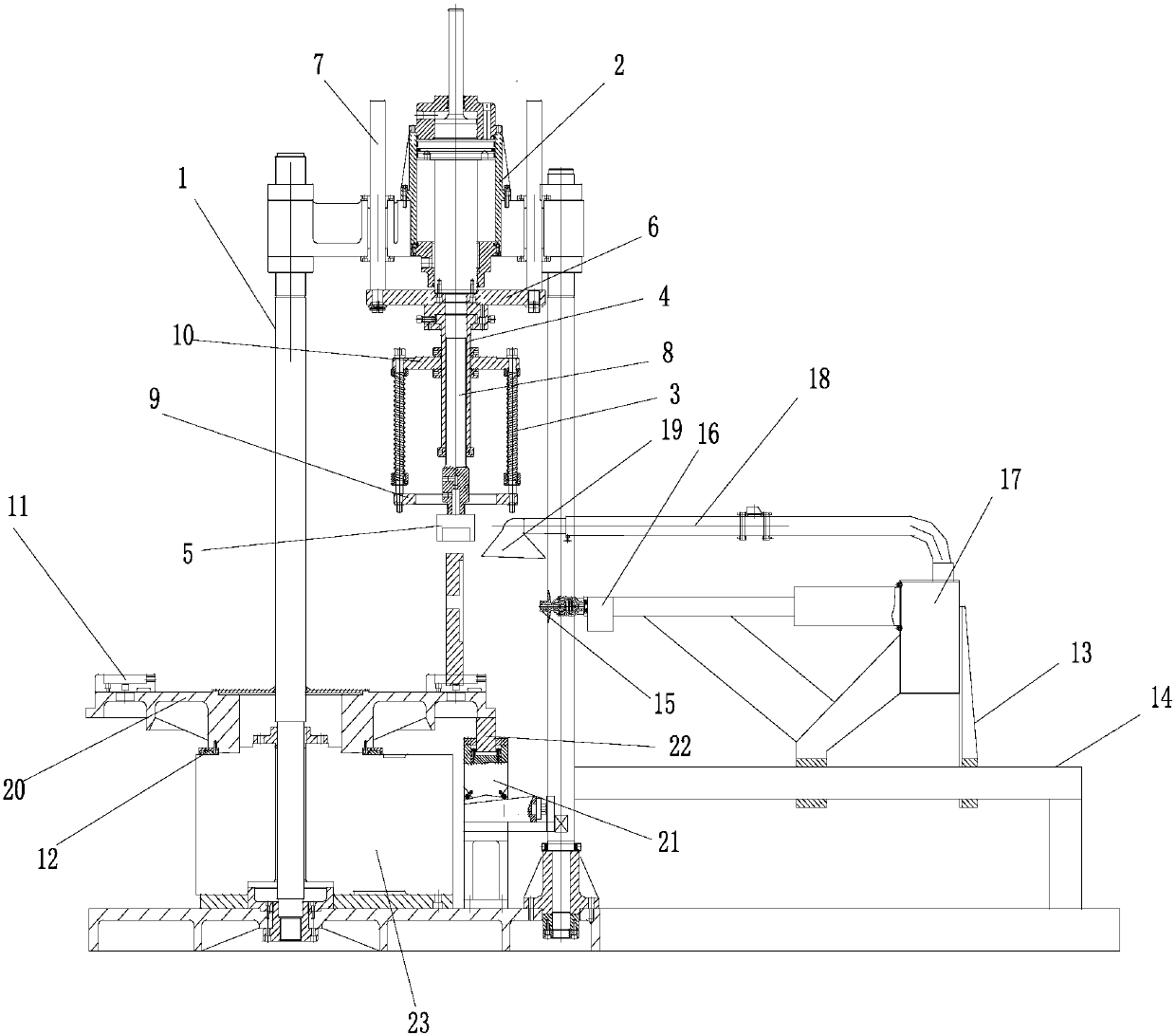
The invention belongs to the technical field of power cable clamping devices, and particularly relates to an automatic grinding device for strain clamp parts. The automatic grinding device comprises aclamping device, a rotating platform and a grinding device body; and the clamping device comprises a bracket, an air cylinder, a spring, a fixing sleeve and an upper pressing seat. According to the automatic grinding device for the strain clamp parts, working efficiency can be greatly improved, and more than 30 parts can be machined in one hour; and grinding and cleaning are conducted through corresponding dust collecting covers, grinding and cleaning are efficient and reliable, the grinding effect is good, dust flying can be avoided and dust can be timely cleaned, and production safety is ensured.

Description

technical field [0001] The invention belongs to the technical field of power cable clamping devices, and in particular relates to an automatic grinding device for tension clamp parts. Background technique [0002] At present, there are mainly three kinds of devices for fixing and clamping the steel-reinforced aluminum stranded wire in domestic transmission line connection clamps. One is wire plugging, the contact surface is small and the plugging is not strong, and the wires are prone to heat; the other is aluminum tube hydraulic pressure. When installing, the wires at both ends are inserted into the aluminum tube, and then pressurized with a hydraulic tool, but the contact surface is small and the grip is not strong; The impact force changes the metallographic phase, the mechanical strength is reduced, and the explosion is not safe. At present, due to the special structure of the wire clip, in order to facilitate the subsequent installation of the cast wire clip, it is nec...

Claims


Application Information

Patent Timeline
IPC IPC(8): B24B5/48B24B55/06B24B5/35B24B41/06B24B41/02B24B49/00
Inventor 蔡威仝猛仝合泽朱友富
Owner 徐州宇飞电力科技有限公司
Learn More