Pipe column structure for CO2 flooding gas injection process

A process string and flooding technology, applied in the directions of sealing/packing, wellbore/well components, production fluid, etc., can solve the problems of short validity period of completion string, heavy maintenance workload, poor air tightness of the string, etc. , to achieve the effect of good air tightness, high working efficiency and reliable sealing

Active Publication Date: 2018-01-19
PETROCHINA CO LTD
View PDF12 Cites 5 Cited by
  • Summary
  • Abstract
  • Description
  • Claims
  • Application Information

AI Technical Summary

Problems solved by technology

At present, some completion strings implemented in China use foreign Baker Hughes, Halliburton and other downhole tools, which are extremely expensive. The completion strings of domestic oil service companies have a short validity period, heavy post-maintenance workload, and high operating costs. , which is mainly reflected in the poor airtightness of the pipe string, and the lifting and lowering of the pipe string must be equipped with a pressurized operation device or a well-killing hydraulic well

Method used


Image

  • Pipe column structure for CO2 flooding gas injection process
  • Pipe column structure for CO2 flooding gas injection process

Examples


Embodiment Construction

[0024] The present invention will be further described below in conjunction with the accompanying drawings.

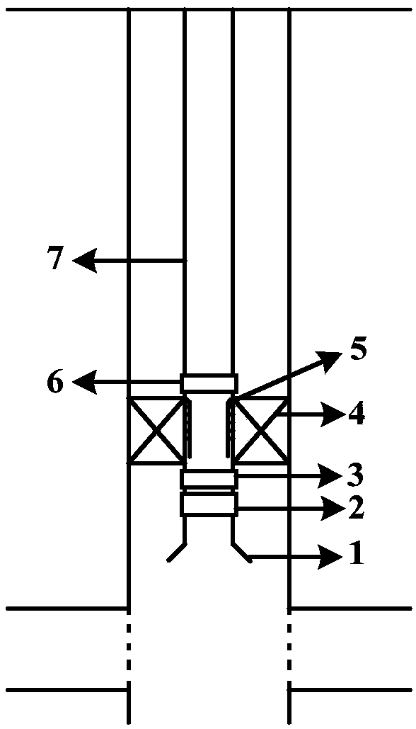
[0025] like figure 1 As shown, the present invention provides a CO 2 The pipe string structure of flooding and gas injection process includes guide shoe 1, check valve 2, setting ball seat 3, Y445 packer 4, cannula 5, reverse circulation valve 6 and tubing 7; The valve 2 is connected, the upper end of the check valve 2 is connected to the setting ball seat 3, the upper end of the setting ball seat 3 is connected to the Y445 packer 4, the Y445 packer 4 is connected to the intubation tube 5, and the upper end of the intubation tube 5 is connected to the reverse circulation in turn Valve 6 and tubing 7.

[0026] Among them, the connection button type of the pipe string structure of the present invention is a BGT button, and the annular space is an oil-based protective fluid. The Y445 packer 4 is mainly used as a permanent downhole tool, and the intubation tube 5 is used...


PUM


Abstract

The invention discloses a pipe column structure for the CO2 flooding gas injection process. The pipe column structure comprises a guiding shoe, a check valve, a setting ball seat, a Y445 packer, an inserting pipe, a reverse circulation valve and an oil pipe. The guiding shoe is connected with the check valve; the upper end of the check valve is connected with the setting ball seat; the upper end of the setting ball seat is connected with the Y445 packer; the Y445 packer is connected with the inserting pipe; and the upper end of the inserting pipe is connected with the reverse circulation valveand the oil pipe in sequence. During working, the parts are connected in sequence, a pipe column is put downwards, an annulus is filled with a conventional oil-based annulus protection fluid in a reverse circulation mode, a quick-dissolving soluble ball is put, pressure injection for setting is conducted, and thus gas can be injected normally; when the pipe column is taken out, through the checkvalve, the oil pipe is directly emptied so that pressure can be released, the pipe column is lifted up, the inserting pipe is pulled out, and thus a pipe string can be taken out; if pressure relief ofthe oil pipe fails, a well killing fluid is injected in a reverse circulation mode for well killing, then the pipe column is lifted up, and thus the pipe string can be taken out; after pipe string checking work, the parts are connected in sequence, the pipe column is put downwards, the inserting pipe is inserted into the packer, and thus sealing well-completion can be conducted.

Description

technical field [0001] The present invention relates to a CO 2 The string structure of flooding and gas injection process is suitable for oilfield CO 2 Flooding injection well completion. Background technique [0002] In recent years, CO 2 As a technology that can effectively improve the recovery of low-permeability reservoirs, oil flooding has been developed rapidly. 2 Oil flooding is a new technology that can both enhance oil recovery and reduce carbon emissions. Domestic and foreign indoor experiments and field tests have shown that CO 2 Flooding can increase the recovery of low permeability reservoirs by 7% to 15%. Low-permeability reservoirs in China are rich in reserves, and the grade of newly added reserves is getting worse year by year. Some reservoirs are difficult to produce by water flooding, and the production effect is poor. Compared with water flooding, CO 2 Flooding has the advantages of quickly replenishing formation energy, increasing swept volume and...

Claims


Application Information

Patent Timeline
Patent Type & Authority Applications(China)
IPC IPC(8): E21B43/16E21B33/12
Inventor 刘忠能黄伟王在强赵广民郭思文薛晓伟任勇蒙鑫谭俊领石海霞刘明
Owner PETROCHINA CO LTD
Why Eureka
Try Eureka