Hydraulic oil tank and hot melting kettle thereof
A technology of hydraulic oil tank and hot melt kettle, which is used in oil supply tank device, heat treatment, fluid pressure actuating device, etc. Avoid aging, avoid the effect of reducing viscosity
- Summary
- Abstract
- Description
- Claims
- Application Information
AI Technical Summary
Problems solved by technology
Method used
Image
Examples
Embodiment 1
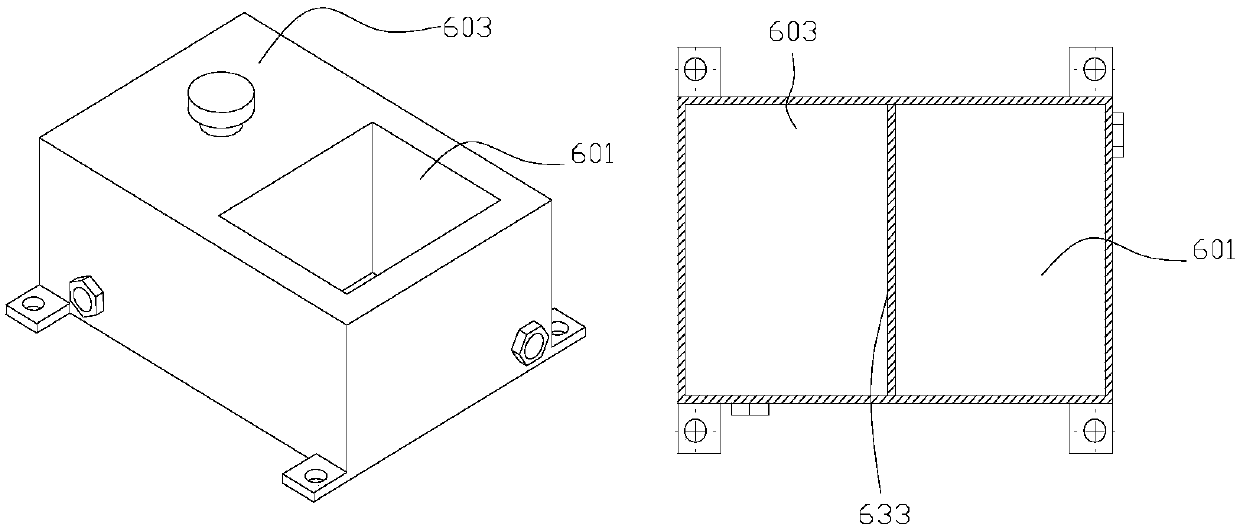
[0032] Example 1: Reference figure 1 , wherein, the right figure is a horizontal cross-sectional view of the left figure, it can be seen from the figure that the gap 625 between the accommodation box 601 and the fuel tank body 603 is the inner cavity of the fuel tank body 603, that is, between the accommodation box 601 and the fuel tank body 603 Separated by the heat-conducting partition 633 , the hydraulic oil is placed in the oil tank body 603 , and its heat is exchanged through the heat-conducting partition 633 and the containing box 601 .
Embodiment 2
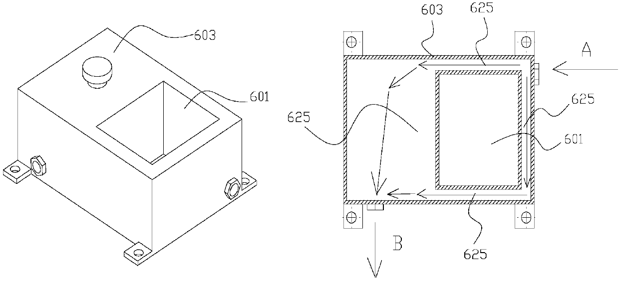
[0033] Example 2: Reference figure 2, wherein, the right figure is a horizontal cross-sectional view of the left figure, it can be seen from the figure that the gap 625 between the accommodation box 601 and the oil tank body 603 is distributed around the side wall of the accommodation box 601 and the hydraulic oil tank is used to connect the oil supply port of the hydraulic system The first connecting port 605 and the second connecting port 606 respectively corresponding to the oil return port are distributed on opposite sides of the containing box 601 . That is, the return oil of the hydraulic system enters the oil tank through the second connection port 606. As indicated by the arrow, the temperature of the hydraulic oil circulated through the hydraulic system is relatively high. When the oil circulates back to the hydraulic oil tank, the direction is as shown in A. The surroundings of the box 601 are gathered together after heat exchange for the B direction to be pumped aw...
Embodiment 3
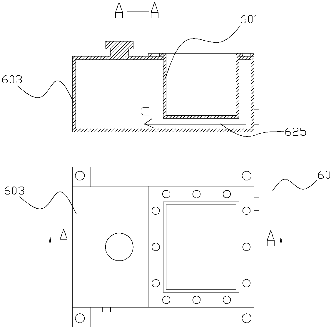
[0034] Example 3: Reference image 3 , wherein, the upper figure is a cross-sectional view at A in the lower figure. On the basis of Embodiment 2, there is also a gap between the bottom of the housing box 601 and the inner wall of the fuel tank body 603 . In this way, compared with Embodiment 2, there is one more return flow C of the hydraulic oil, that is, the bottom surface of the housing box 601 can also perform heat exchange.
[0035] The working heat of the hydraulic system is mainly accumulated in the hydraulic oil tank through the circulation of hydraulic oil. The storage box 601 is embedded in the oil tank body 603 and there is a gap between them for the hydraulic medium to flow through. The oil can flow through the gap in the oil tank body 603, immerse the back of the holding tank and flow through the outer wall of the holding chamber 601, that is to say, the heat of the hydraulic oil can be transferred to the holding chamber, and the water can be absorbed by filling ...
PUM
 Abstract
Description
Claims
Application Information
 - R&D
- Intellectual Property
- Life Sciences
- Materials
- Tech Scout
- Unparalleled Data Quality
- Higher Quality Content
- 60% Fewer Hallucinations
Browse by: Latest US Patents, China's latest patents, Technical Efficacy Thesaurus, Application Domain, Technology Topic, Popular Technical Reports.
© 2025 PatSnap. All rights reserved.Legal|Privacy policy|Modern Slavery Act Transparency Statement|Sitemap|About US| Contact US: help@patsnap.com


