Active phased array radar reception channel correction method based on fixed ground object echo

A phased array radar and receiving channel technology, applied in the field of radar, can solve the problems of small calculation amount, will produce errors, high application conditions and other problems, and achieve the effect of ensuring effectiveness, easy operation, and avoiding estimation deviation.

Active Publication Date: 2018-01-19
CNGC INST NO 206 OF CHINA ARMS IND GRP
View PDF4 Cites 10 Cited by
  • Summary
  • Abstract
  • Description
  • Claims
  • Application Information

AI Technical Summary

Problems solved by technology

Channel error correction methods can be divided into two types: internal correction method and external correction method. The internal correction method uses additional equipment to achieve correction in the antenna system, which increases the complexity and cost of the system.
The external calibration methods mainly include active calibration and self-calibration. Active calibration is to place one or more signal sources with known angles in the mid-field or far-field of the radar array. Due to the location accuracy of the signal source, for the external field environment where the radar works, the measurement of the correction source direction will inevitably produce errors, and the radiation source needs to be set up because of the active correction, which also increases the operational burden.
Existing self-calibration methods are usually based on existing independent signal sources in space, and use some optimization model to jointly estimate the source angle and array amplitude-phase error to realize the correction of receiving array errors. These methods not only There are certain requirements for the number of signal sources, and the non-correlation of each source signal is required, which has high requirements for application conditions. In addition, the high-dimensional and nonlinear optimization corresponding to the joint estimation of parameters brings a huge amount of computation, thus Affects the applicability of existing self-calibration methods

Method used


Image

  • Active phased array radar reception channel correction method based on fixed ground object echo
  • Active phased array radar reception channel correction method based on fixed ground object echo
  • Active phased array radar reception channel correction method based on fixed ground object echo

Examples


Embodiment Construction

[0054] Now in conjunction with embodiment, accompanying drawing, the present invention will be further described:

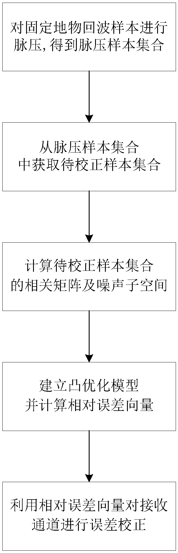
[0055] refer to figure 1 , the specific implementation steps of this embodiment are as follows:

[0056] Step 1. Perform pulse compression on the echo data of fixed surface objects to obtain a pulse pressure sample set.

[0057] Assuming that the active phased array radar contains M receiving elements, that is, the radar contains M receiving channels, then when the receiving beam points to θ 0 direction, the receiving pattern can be expressed as

[0058] B(θ k ,θ 0 )=|a H (θ k )diag(w)a(θ 0 )| 2 , k=1,...,K

[0059] where θ 0 Indicates the direction of the receiving beam, a(θ k ) means θ k The steering vector of the direction, whose dimension is M×1, Indicates the discrete sampling angle, K indicates the number of discrete sampling angles, (·) H Indicates conjugate transpose, |·| indicates modulus, vector w indicates the magnitude weight vector wit...


PUM


Abstract

The invention relates to an active phased array radar reception channel correction method based on fixed ground object echoes, and mainly solves the problems that active phased array radar reception channel correction is complicated to operate, relies on auxiliary sources or the like in an outfield working condition. The method is realized by the following steps: firstly, applying pulse pressure to fixed ground object echoes and obtaining a pulse pressure sample set; secondly, carrying out primary election, peak value alignment and correlation screening on the pulse pressure sample set, and obtaining a to-be-corrected sample set; thirdly, calculating a correlation matrix and a noise sub-space of the to-be-corrected sample set; fourthly, establishing a convex optimization model on the basisof orthogonality of the sub-space and solving a relative error vector; and fifthly, conducting error correction on a reception channel through the relative error vector. Good estimation of amplitudephase errors of the reception channel is obtained without construction of auxiliary sources, sidelobe levels of a radar receiving pattern are reduced, and the method can be used for reception channelcorrection of an active phased array radar outfield working environment.

Description

technical field [0001] The invention belongs to the technical field of radar, relates to the error correction of the receiving channel of the radar array, can be used for the error correction of the receiving channel of the active phased array radar in the field working environment, and meets the engineering requirements. Background technique [0002] Phased array radar realizes the beam with specific direction, gain and sidelobe level by adjusting the signal phase of each array element, and then realizes the desired power coverage and spatial filtering. However, due to the use of active devices, the receiving channels of each array element will usually have inconsistencies over time and in different environments, which will lead to high side lobes in the pattern generated by the receiving beamforming, and high side lobes will not only cause side lobes The entry of strong clutter in the area will cause false alarms, and at the same time, interference suppression will not be ...

Claims


Application Information

Patent Timeline
Patent Type & Authority Applications(China)
IPC IPC(8): G01S7/32G01S7/40
Inventor 王旭蔡兴雨朱思桥任伦周游兑雅娟李斌袁朋杰
Owner CNGC INST NO 206 OF CHINA ARMS IND GRP
Why Eureka
Try Eureka