
A method for improving the luminous efficiency of high-voltage LED chips

A technology of LED chips and luminous efficiency, applied in semiconductor devices, electrical components, circuits, etc., can solve the problems of difficult control of dry etching process, large proportion of groove area, easy short-circuit and disconnection of products, etc., to achieve easy control, Increase the luminous area and the effect of small proportion

Active Publication Date: 2019-06-25
宁波安芯美半导体有限公司
View PDF4 Cites 0 Cited by
  • Summary
  • Abstract
  • Description
  • Claims
  • Application Information

AI Technical Summary

Problems solved by technology

[0005] In view of the above-mentioned shortcomings of the prior art, the purpose of the present invention is to provide a method for improving the luminous efficiency of high-voltage LED chips, which is used to solve the problems of large groove area ratio, small luminous surface, and low luminous efficiency in the current high-voltage LED chip manufacturing process. Low cost, difficult control of dry etching process and easy short-circuit and disconnection of products

Method used

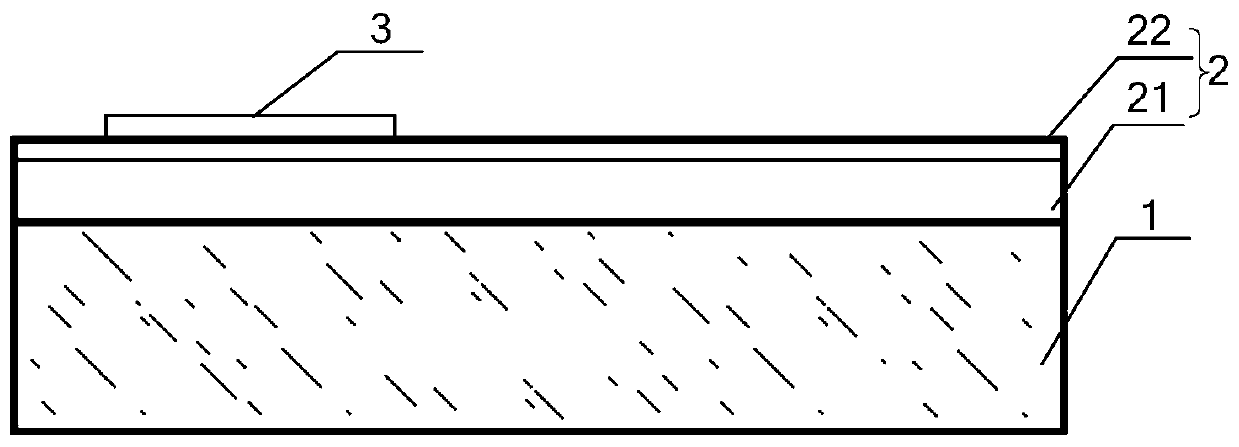
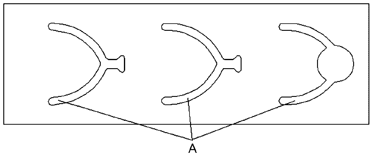

Image

  • A method for improving the luminous efficiency of high-voltage LED chips
  • A method for improving the luminous efficiency of high-voltage LED chips
  • A method for improving the luminous efficiency of high-voltage LED chips

Examples


Embodiment Construction

[0056] Embodiments of the present invention are described below through specific examples, and those skilled in the art can easily understand other advantages and effects of the present invention from the content disclosed in this specification. The present invention can also be implemented or applied through other different specific implementation modes, and various modifications or changes can be made to the details in this specification based on different viewpoints and applications without departing from the spirit of the present invention. It should be noted that, in the case of no conflict, the following embodiments and features in the embodiments can be combined with each other.

[0057] It should be noted that the diagrams provided in the following embodiments are only schematically illustrating the basic ideas of the present invention, although only the components related to the present invention are shown in the diagrams rather than the number, shape and shape of the ...


PUM


Abstract

The invention provides a method for improving light-emitting efficiency of a high-voltage LED chip. The method comprises the steps 1, growing SiO2 to form a current barrier layer (CBL), and photoetching the CBL to obtain a first designated pattern; 2, growing ITO, performing Mesa photoetching, performing Mesa photoetching after corrosion of the ITO, and photoetching a second designated pattern; 3,photoetching a third designated pattern, and controlling an angle of an inclined surface of an etching groove to be 60-85 degrees; 4, growing an insulation layer SiO2, removing remaining SiO2, and reserving the SiO2 at a bridging part and a part of a light-emitting surface to obtain a fourth designated pattern; 5, filling the groove with positive photoresist, and making a fifth designated pattern; and 6, photoetching a sixth designated pattern by employing negative photoresist, and evaporating PN electrode metal. By the preparation method, ITO photoetching and MESA photoetching are combined,the insulation layer photoetching and the passivation layer SiO2 photoetching are combined, and the flow is simplified; the groove area is small, the light-emitting area is expanded, and the light-emitting efficiency is improved; the dry etching process is easier to control, and an electric leakage potential of a broken line is prevented, the voltage is reduced, and the working lifetime of a product is prolonged.

Description

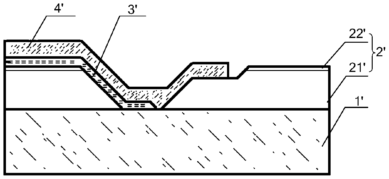
technical field [0001] The invention relates to the field of LED chip manufacturing, in particular to a method for improving the luminous efficiency of a high-voltage LED chip. Background technique [0002] High-voltage (HV) LED chips are made by connecting multiple chips in series to emit light in the LED chip preparation stage, reducing the number of welding wires in downstream packaging factories, improving their production efficiency and saving costs, and the reliability of the package increases with the reduction in the number of welding wires. promote. [0003] To achieve series connection of high-voltage chips, GaN must be divided into several units, and the units must be insulated. This is the biggest difference between high-voltage chips and ordinary chips. Such as figure 1 As shown, it is a partial side view of the trench formed by the high-voltage chip preparation method in the prior art. At present, the high-voltage chip is divided by dry etching of the GaN lay...

Claims


Application Information

Patent Timeline
Patent Type & Authority Patents(China)
IPC IPC(8): H01L33/38H01L33/44
Inventor 潘尧波吴永军刘亚柱唐军吕振兴
Owner 宁波安芯美半导体有限公司
Learn More