Mixed lossy duplexer

A duplexer and filter technology, applied in the field of satellite communication systems, can solve the problems of low in-band flatness and no involvement, and achieve the effects of improving in-band flatness, improving frequency selectivity, and improving in-band flatness

Active Publication Date: 2018-01-19
上海卷积通讯技术有限公司
View PDF3 Cites 6 Cited by
  • Summary
  • Abstract
  • Description
  • Claims
  • Application Information

AI Technical Summary

Problems solved by technology

The problem of passband flatness of duplexers is not involved in the existing recorded technology, for example, application publication number CN 103633400 A, a patent application titled "a microstrip duplexer based on electromagnetic hybrid coupling", discloses a Electromagnetic hybrid coupling microstrip duplexer, including double-sided copper-clad microstrip board, two filters with controllable passband frequency and bandwidth, and the first port feeder are fabricated on the same side of the double-sided copper-clad microstrip board , the second port feeder, T-shaped connector, the first port, the second port, the third port, the other side of the double-sided copper-clad microstrip board is a copper-clad grounding board; the two filters are mainly composed of three It is composed of mutually coupled quarter-wavelength microstrip resonators, and there is a grounding hole at the phase connection at one end of the three microstrip resonators, and there is electrical coupling between two adjacent microstrip resonators in each filter, although There are transmission zeros on both sides of the passband of the duplexer, which improves the frequency selectivity of the duplexer, but the flatness in the band is low and does not involve any improvement technology

Method used


Image

  • Mixed lossy duplexer
  • Mixed lossy duplexer
  • Mixed lossy duplexer

Examples


Embodiment Construction

[0029] The present invention will be described in further detail below in conjunction with the accompanying drawings and specific embodiments.

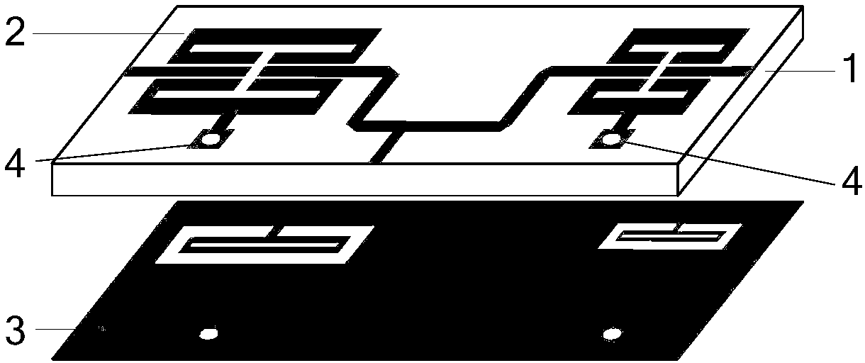
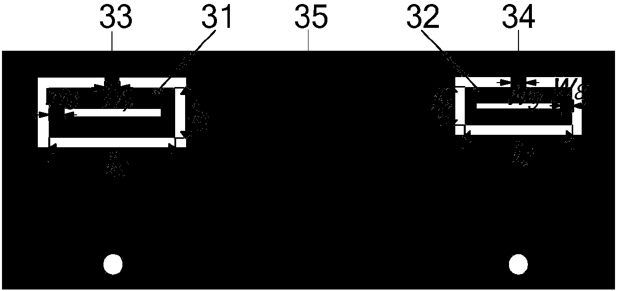
[0030] refer to figure 1 , a hybrid lossy duplexer, the dielectric substrate 1 is a rectangular dielectric plate with a dielectric constant of 10.2 and a thickness of 1.27mm, the composite microstrip line structure 2 is printed on the upper surface of the dielectric plate 1 and the coplanar waveguide structure 3 Printed on the lower surface of the dielectric board 1, the two structures form a microstrip-coplanar waveguide layered hybrid structure.

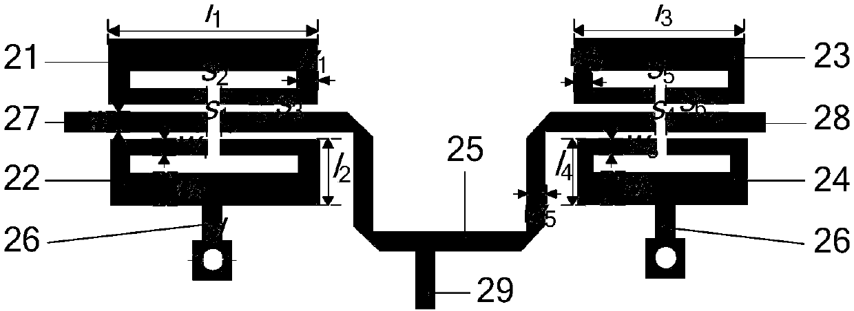
[0031] The composite microstrip line structure 2 has a structure such as figure 2As shown, it includes a first microstrip open-loop resonator 21, a second microstrip open-loop resonator 22, a third microstrip open-loop resonator 23, a fourth microstrip open-loop resonator 24, a first port feeder 27, The second port feeder 28 and the common port feeder 29; the first microstrip open-loop ...


PUM


Abstract

The present invention provides a mixed lossy duplexer, wherein a transmission zero point is individually controllable and the miniaturization is realized. Meanwhile, the in-band flatness of the duplexer is improved. The mixed lossy duplexer comprises a dielectric substrate, a composite micro-strip line structure printed on the upper surface of the dielectric substrate, and a coplanar waveguide structure arranged on the lower surface of the dielectric substrate. The composite micro-strip line structure includes three port feeder lines, four micro-strip open-loop resonators and a curved micro-strip line. The three port feeder lines are connected through the curved micro-strip line. The coplanar waveguide structure comprises two coplanar waveguide ring resonators, and the two coplanar waveguide ring resonators form a micros-strip line and coplanar waveguide hierarchical hybrid structure, wherein every two identical micro-strip open-loop resonators and one coplanar waveguide ring resonatorform a non-uniform Q-value resonator channel filter. Inconsistent resonator Q-values can improve the in-band flatness and then the ground patch resistance is introduced by the micro-strip open-loop resonators. The Q values of the resonators are reduced and the in-band flatness is further improved.

Description

technical field [0001] The invention belongs to the field of electronic communication, and relates to a hybrid lossy duplexer, which can be used in a wireless communication system, especially a satellite communication system, which requires high in-band flatness and high frequency selectivity. Background technique [0002] In a wireless communication system, a radio frequency transceiver and an antenna are connected together to complete the processing work of receiving and sending signals. If the receiver and the transmitter are each connected with an antenna, not only the circuit size and cost will increase, but also the two antennas will interfere with each other, reducing the stability and reliability of the system. The duplexer can enable the transceiver to share a pair of antennas for transmitting and receiving, which significantly reduces mutual interference, so it has a wide range of applications. [0003] A duplexer is a three-port network consisting of two filters ...

Claims


Application Information

Patent Timeline
Patent Type & Authority Applications(China)
IPC IPC(8): H01P1/203
Inventor 肖建康张宁戚兴
Owner 上海卷积通讯技术有限公司
Why Eureka
Try Eureka