Antenna system and mobile terminal

An antenna system and mobile terminal technology, applied in the electronic field, can solve the problems of consuming space resources, unable to reuse antennas, MIMOWIFI and LTE antennas are not compatible, and achieve the effect of improving sensitivity

Inactive Publication Date: 2018-01-19
VIVO MOBILE COMM CO LTD
View PDF3 Cites 10 Cited by
  • Summary
  • Abstract
  • Description
  • Claims
  • Application Information

AI Technical Summary

Problems solved by technology

[0006] The present invention provides an antenna system and a mobile terminal to solve the problem that the MIMO system existing in the existing antenna system solution cannot

Method used


Image

  • Antenna system and mobile terminal
  • Antenna system and mobile terminal
  • Antenna system and mobile terminal

Examples


Embodiment 1

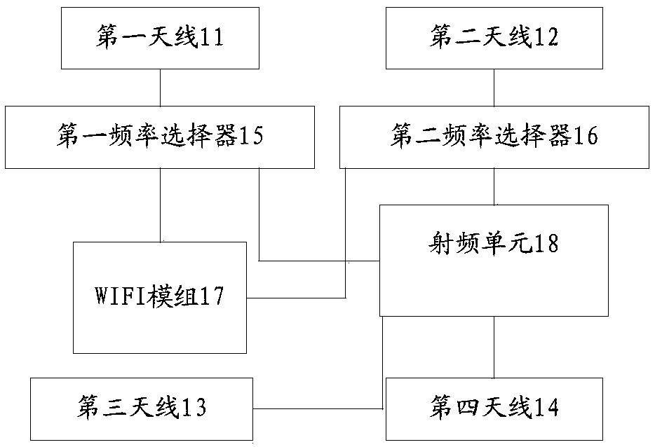
[0019] refer to figure 1 , shows a schematic structural diagram of an antenna system according to Embodiment 1 of the present invention.

[0020] The antenna system of the embodiment of the present invention can be applied to a mobile terminal, and the antenna system can include: a first antenna 11, a second antenna 12, a third antenna 13, a fourth antenna 14, a first frequency selector 15, and a second frequency selector 16. WIFI module 17 and radio frequency unit 18.

[0021] Wherein, the first antenna 11 can be connected with the WIFI module 17 and the radio frequency unit 18 through the first frequency selector 15, the second antenna 12 can be connected with the WIFI module 17 and the radio frequency unit 18 through the second frequency selector 16, and the third The antenna 13 and the fourth antenna 14 are respectively connected to the radio frequency unit 18 .

[0022] The first frequency selector 15 and the second frequency selector 16 can be extractors / combiners, and...

Embodiment 2

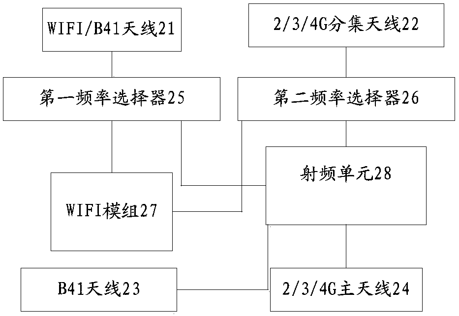
[0029] refer to figure 2 , shows a schematic structural diagram of an antenna system according to Embodiment 2 of the present invention.

[0030] In the antenna system of the embodiment of the present invention, the first antenna is WIFI / B41 antenna 21, the second antenna is 2 / 3 / 4G diversity antenna 22, the third antenna is B41 antenna 23, and the fourth antenna is 2 / 3 / 4G main antenna twenty four.

[0031] Wherein, the WIFI / B41 antenna 21 is respectively connected with the WIFI module 27 and the radio frequency unit 28 through the first frequency selector 25, and the 2 / 3 / 4G diversity antenna 22 is respectively connected with the WIFI module 27 and the radio frequency unit through the second frequency selector 26. The unit 28 is connected, and the B41 antenna 23 and the 2 / 3 / 4G main antenna 34 are connected to the radio frequency unit 28 respectively.

[0032] Wherein, the signals received by the WIFI / B41 antenna include WIFI frequency band signals (2400MHz-2500MHz, 5735MHz-5...

Embodiment 3

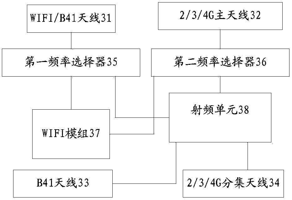
[0041] refer to image 3 , shows a schematic structural diagram of an antenna system according to Embodiment 3 of the present invention.

[0042] The first antenna in the antenna system of the embodiment of the present invention is WIFI / B41 antenna 31, the second antenna is 2 / 3 / 4G main antenna 32, the third antenna is B41 antenna 33, and the fourth antenna is 2 / 3 / 4G diversity Antenna34.

[0043] Wherein, the WIFI / B41 antenna 31 is respectively connected to the WIFI module 37 and the radio frequency unit 38 through the first frequency selector 35, and the 2 / 3 / 4G main antenna 32 is respectively connected to the WIFI module 37 and the radio frequency unit through the second frequency selector 36. The unit 38 is connected, and the B41 antenna 33 and the 2 / 3 / 4G diversity antenna 34 are connected to the radio frequency unit 38 respectively.

[0044] Wherein, the signals received by the WIFI / B41 antenna include WIFI frequency band signals (2400MHz-2500MHz, 5735MHz-5850MHz) and B41 ...


PUM


Abstract

The invention provides an antenna system applied to a mobile terminal. The system comprises a first antenna, a second antenna, a third antenna, a fourth antenna, a first frequency selector, a second frequency selector, a WIFI module and a radio frequency unit, wherein the first antenna is connected with the WIFI module and the radio frequency unit through the first frequency selector; the second antenna is connected with the WIFI module and the radio frequency unit through the second frequency selector; and the third antenna and the fourth antenna are connected to the radio frequency unit separately. The antenna system can be designed through the first frequency selector and the second frequency selector, signals of different bands received by the antennas can be received and transmitted to the corresponding WIFI module and radio frequency unit separately, radiation bandwidths of the antennas can be effectively utilized to achieve a multi-antenna system, and furthermore, an MIMO WIFI can be well compatible with an LTE antenna to improve the sensitivity of LTE.

Description

technical field [0001] The invention relates to the field of electronic technology, in particular to an antenna system and a mobile terminal. Background technique [0002] With the popularity of smartphones, the use of WiFi is becoming more and more widespread. As people have higher and higher requirements for the timeliness of accessing the network, Multi-input Multi-output (MIMO) technology and corresponding chips are more and more applied to mobile phone products, and WiFi data transmission technology is gradually changing from a single Antenna to multi-antenna transition. [0003] The continuous improvement of wireless access rate is a market demand, and MIMO antenna design has become an industry trend. Due to the stacking limitations of terminal modules and devices, and the limitation of multi-antenna isolation, MIMO antenna design has become a difficult point in terminal product design. [0004] In the existing technical solutions, the MIMO antennas in the mobile te...

Claims


Application Information

Patent Timeline
IPC IPC(8): H01Q1/36H01Q1/24H01Q21/00H01Q23/00H04M1/02
Inventor 侯梓鹏
Owner VIVO MOBILE COMM CO LTD
Why Eureka
Try Eureka