

Topological structure of high-power density power electronic transformer and control method for topological structure
A high power density, power electronics technology, applied in the field of power transformation, can solve the problems of high cost, low power density, large volume, etc.
- Summary
- Abstract
- Description
- Claims
- Application Information
AI Technical Summary
Problems solved by technology
Method used
Image

Examples
Embodiment 1
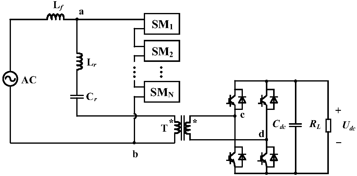
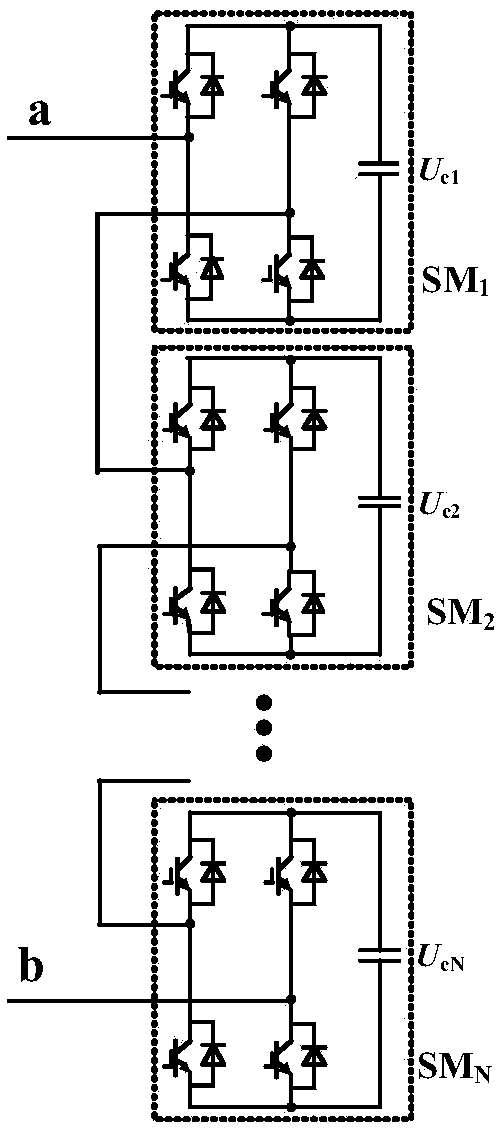
[0070] like figure 1 The high power density power electronic transformer topology shown is composed of a high-voltage AC stage, a high-frequency isolation transformer, and a low-voltage DC stage. The high-voltage AC stage adopts a new topology, and the high-voltage AC power supply passes through the filter inductor L f After that, it is connected to the input terminal a of N cascaded full-bridge sub-modules, and the input terminal a is connected to the middle point of the left bridge arm of the first full-bridge sub-module. like figure 2 As shown, the middle point of the right bridge arm of the first full-bridge sub-module is connected to the middle point of the left bridge arm of the second full-bridge sub-module, and so on, the middle of the right bridge arm of the N-1th full-bridge sub-module point is connected to the middle point of the left bridge arm of the Nth full-bridge sub-module, and the middle point of the right bridge arm of the N-th full-bridge sub-module is co...
Embodiment 2
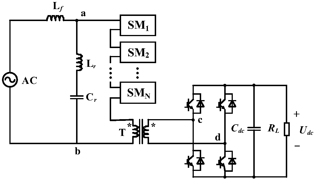
[0072] This example is extended and changed on the basis of the first example. The entire topology is still composed of a high-voltage AC stage, a high-frequency isolation transformer, and a low-voltage DC stage, such as image 3 shown. High-voltage AC power passes through the filter inductor L f Connect to the input terminal a of N cascaded full-bridge submodules afterwards, the structure of N cascaded full-bridge submodules is consistent with that described in Embodiment 1, and the output of N cascaded full-bridge submodules is the same as the high The same-named end of the primary side of the frequency isolation transformer is connected, and the different-named end of the original side of the high-frequency isolation transformer is connected back to the high-voltage AC power supply. L r C r One end of the series resonant circuit is connected to the input end a of the N cascaded full-bridge sub-modules, and the other end is connected to the different-named end b of the p...
Embodiment 3
[0075] like Figure 4 (a), Figure 4 As shown in (b), the entire topology is still composed of a high-voltage AC stage, a high-frequency isolation transformer, and a low-voltage DC stage, and the number of cascaded full bridges on the high-voltage side, LC series circuits, high-frequency isolation transformers, and H-bridges on the low-voltage side The number is multiples of the topology described in Embodiment 1 or Embodiment 2. When two bridge arms of each phase of the high-voltage AC stage circuit are connected in series with the topological structures described in Embodiment 1, each phase of the bridge arm of the high-voltage AC stage circuit is composed of 2N cascaded full-bridge sub-modules. High-voltage AC power passes through the filter inductor L f Then connect to the input terminal a1 of 2N cascaded full-bridge sub-modules, the structure of the 2N cascaded full-bridge sub-modules is consistent with that described in Embodiment 1, and the output terminal b2 of the 2...
PUM
 Abstract
Description
Claims
Application Information