evaporative burner

An evaporative, burner technology, applied in the direction of burner, combustion type, combustion method, etc., to reduce incomplete combustion, prolong life, and improve ignitability.

Active Publication Date: 2019-09-10
SANGO CO LTD
View PDF3 Cites 0 Cited by
  • Summary
  • Abstract
  • Description
  • Claims
  • Application Information

AI Technical Summary

Problems solved by technology

In addition, as a third problem, there is a problem of reducing air shortage that causes incomplete combustion of fuel on the downstream side of the combustion chamber.

Method used


Image

  • evaporative burner
  • evaporative burner
  • evaporative burner

Examples


Embodiment 1

[0078] "constitute"

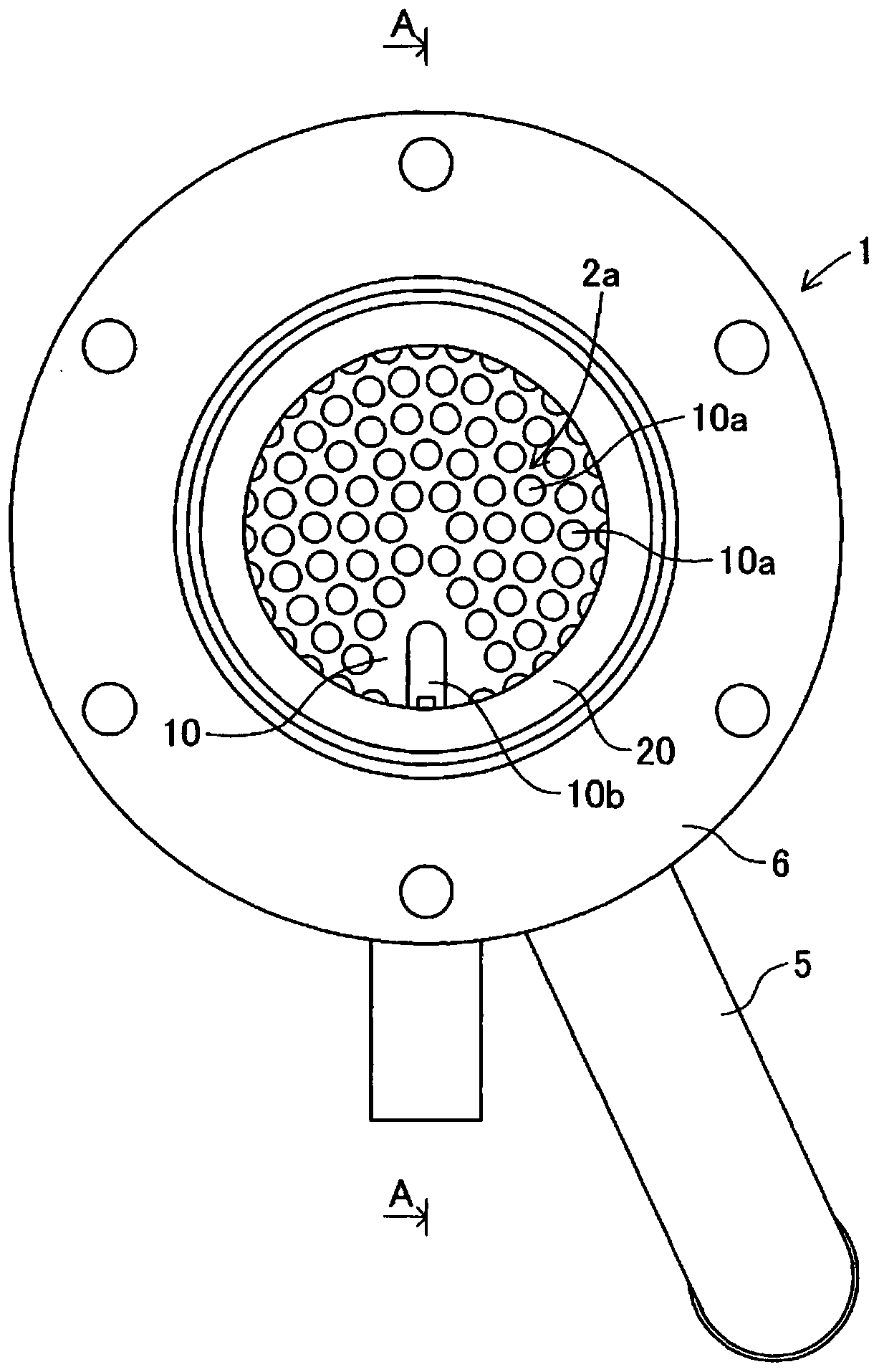
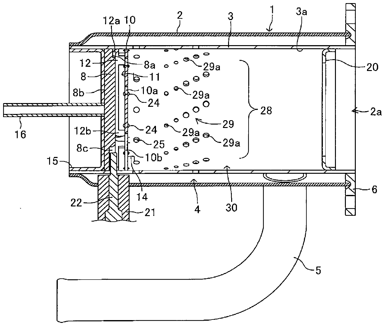
[0079] figure 1 It is a schematic diagram which shows the state which looked at the evaporative burner 1 of Example 1 of this invention from a downstream side. figure 2 Yes figure 1 A-A line sectional view. In the following description, the upper side in the vertical direction ( figure 1 as well as figure 2 The upper side of the paper surface) is referred to as "upper", and the opposite side, that is, the lower side, is referred to as "lower". In addition, towards figure 2 On the paper, let the left side be the "upstream side", and the opposite side, that is, the right side, shall be the "downstream side".

[0080]The evaporative burner 1 includes an outer casing 2 and an inner casing 3 arranged inside the outer casing 2 . The shapes of the outer casing 2 and the inner casing 3 are not particularly limited, and can be appropriately designed, for example, according to the application of the evaporative burner 1 and the use environment. In the pr...

Embodiment 2

[0144] As described above, according to the evaporative burner 1 of the first embodiment of the present invention, it is possible to simultaneously solve the first problem and the second problem, that is, the first problem is to supply an amount of air suitable for the ignition device to ignite the fuel to the ignition In order to improve the ignitability of the evaporative burner and prolong the life of the liquid wick, the second problem is to prevent the infiltration of the fuel into the liquid wick and to improve the heat transfer from the ignition mechanism to the liquid wick. Improve the ignitability of evaporative burners.

[0145] The evaporative combustor 1a of the second embodiment of the present invention described below aims to solve the third problem of reducing the air shortage that causes incomplete combustion of fuel on the downstream side of the combustion chamber.

[0146] "Structure and Action"

[0147] The evaporative combustor 1 a is characterized in that...

Embodiment 3

[0166] In the above-described evaporative burners 1 and 1a, the promoting member having a planar (plate-like) shape as a whole is used, except for a partial curved portion. However, in the plate-shaped promoting member, deformation (thermal deformation) of the promoting member may occur due to a temperature change accompanying the combustion of fuel. Therefore, in Example 3 of the present invention, the rigidity (section modulus) of the promotion member is increased, and the thermal deformation of the promotion member accompanying the combustion of the fuel is reduced.

[0167] "structure"

[0168] like Figure 23 As shown, in the evaporative combustor 1b according to the third embodiment of the present invention, the promoting member 50 is constituted by a plate-shaped member having a curved surface shape with a central portion protruding toward the upstream side. In addition, the impregnating member 48 is also constituted by a plate-shaped member having a curved surface sh...


PUM


Abstract

A promotion member is disposed a predetermined distance apart from an impregnation member disposed at an upstream side end of a combustion chamber, and an ignition device and a first air supply opening are prepared on an upstream side from the promotion member in an ignition space, and a second air supply opening is prepared on a downstream side from the promotion member in the ignition space. Fuel is supplied to a smooth surface of the impregnation member, and a concave part or cutout is formed in the impregnation member to house at least a part of the ignition device. A flow rate of air supplied to the combustion space through the second air supply opening becomes larger toward the downstream side. Thereby, ignitability in an evaporation type burner is improved and incomplete combustion of fuel on the downstream side of the combustion chamber is reduced.

Description

technical field [0001] The present invention relates to evaporative burners. Background technique [0002] Conventionally, an evaporative burner is known in which a liquid wick disposed at one end of a combustion chamber is impregnated with fuel, and a glow plug disposed in the vicinity of the liquid wick heats and ignites and combusts the vapor of the fuel generated from the liquid wick. Such an evaporative burner is expected to be used as a heat source in, for example, regeneration of a diesel particulate filter (DPF) mounted on a vehicle using diesel fuel, and a device for heating vehicles and houses. [0003] In addition, although the evaporative burner is provided with an intake port for introducing air for the purpose of burning fuel into the combustion chamber, the glow plug may be cooled by the introduced air, thereby reducing the ignitability of the evaporative burner. . Therefore, it is proposed to provide a windproof member on the side opposite to the liquid cor...

Claims


Application Information

Patent Timeline
Patent Type & Authority Patents(China)
IPC IPC(8): F23D3/40F23Q7/08
CPCF23D3/40F23L1/00F23L9/02F23Q7/08
Inventor 城户大作土屋由弘
Owner SANGO CO LTD
Why Eureka
Try Eureka