
Feeding device of automatic assembly equipment for blades of blade lock

An automatic assembly and blade lock technology, applied in metal processing equipment, metal processing, manufacturing tools, etc., can solve the problems of low production speed, heavy labor, low accuracy, etc., to improve speed and quality, reduce labor costs, The effect of reducing workload

Active Publication Date: 2018-01-23
扬州通扬化工设备有限公司
View PDF5 Cites 10 Cited by
  • Summary
  • Abstract
  • Description
  • Claims
  • Application Information

AI Technical Summary

Problems solved by technology

[0002] Blade lock is a kind of lock with high anti-theft ability among many locks at this stage, and its cost is low, so blade lock is widely used. However, the production technology of blade lock is not perfect now, and its production process is basically semi-automatic. state, especially the loading process of the lock cylinder and blades, the blades are basically loaded manually, and then in the process of mechanical work, the lock cylinder is placed on the mechanical station manually, and then the final assembly is completed by the machine , its production process is still inseparable from manual cooperation, and the amount of labor required is still relatively large. In the process of manual operation, its accuracy is very low compared with that of machines, resulting in a high scrap rate in production, and due to manual Participation leads to low production speed and high labor costs, resulting in high cost. In view of the above problems, a feeding device for automatic blade lock blade assembly equipment is provided.

Method used


Image

  • Feeding device of automatic assembly equipment for blades of blade lock
  • Feeding device of automatic assembly equipment for blades of blade lock
  • Feeding device of automatic assembly equipment for blades of blade lock

Examples


Embodiment Construction

[0024] Below in conjunction with accompanying drawing and embodiment of description, specific embodiment of the present invention is described in further detail:

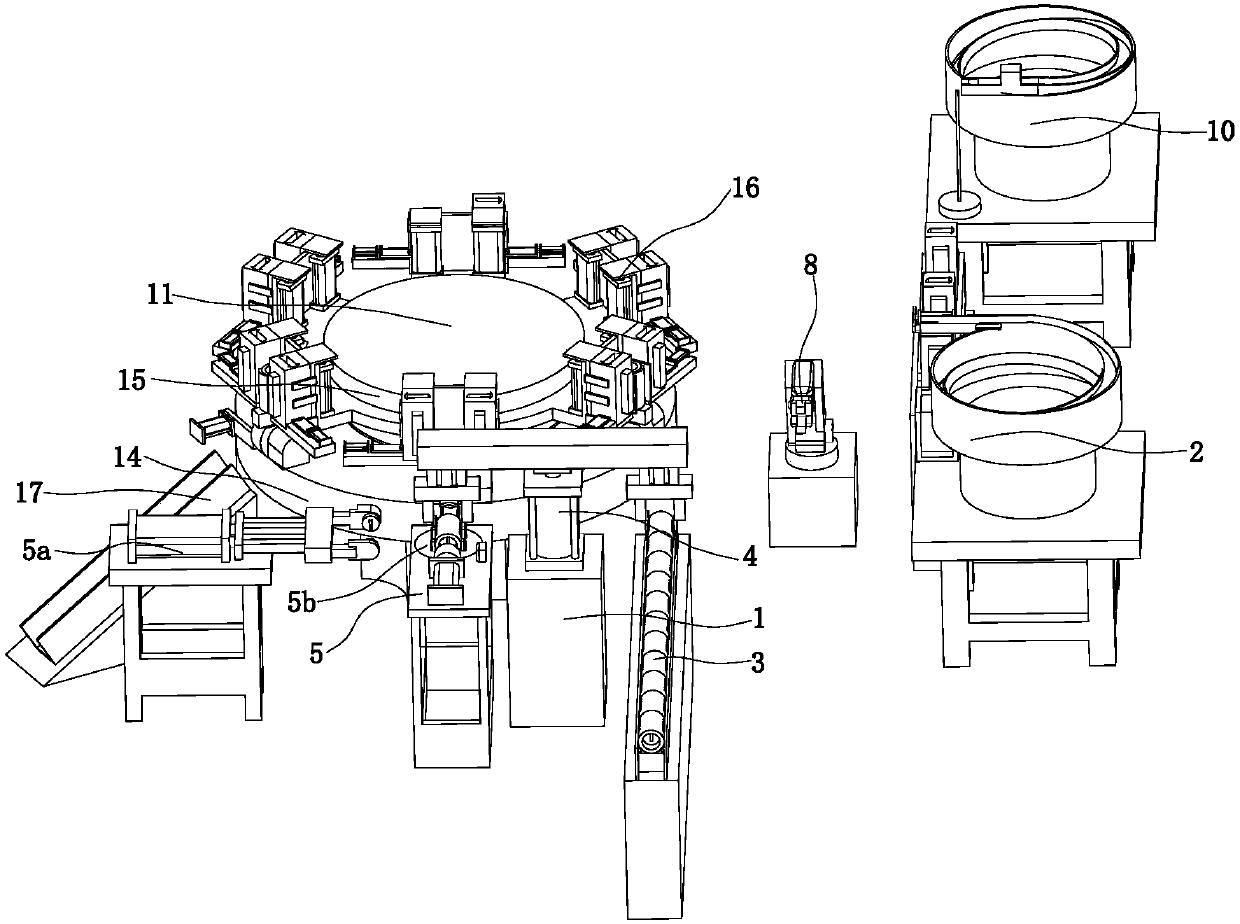
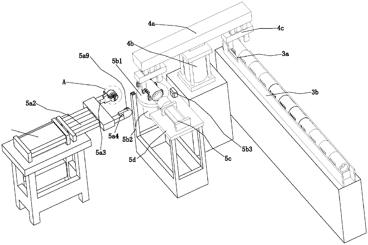
[0025] refer to Figure 1 to Figure 9 The feeding device of a blade lock blade automatic assembly equipment shown includes a first feeding mechanism 1 for lock cylinder feeding, a second feeding mechanism 2 for blade feeding, and a key tooth pattern for scanning The scanning mechanism 10 and the assembly mechanism 11, the first feeding mechanism 1 and the second feeding mechanism 2 are distributed on the side of the assembly mechanism 11 at an angle of 90 degrees, and the scanning mechanism 10 is located on the side of the assembly mechanism 11 The first feeding mechanism 1 includes a first conveying device 3, a transfer device 4 and a transfer device 5, the first transfer device 3 and the transfer device 5 are symmetrically arranged on the side of the transfer device 4, and the second feeding mechanism 2 includes a...


PUM


Abstract

The invention relates to the field of lock production equipment, in particular to a feeding device of automatic assembly equipment for blades of a blade lock. The feeding device comprises a first feeding mechanism and a second feeding mechanism, the first feeding mechanism comprises a first conveying device, a transferring device and a turning device, and the second feeding mechanism comprises a second conveying device, a first vibration feeding disc and a mechanical arm. According to the feeding device, the first vibration feeding disc, the second conveying device and the mechanical arm are matched, the blades are contained into a blade box, the blade box is placed at the working position of assembly, and feeding of the blades is completed; the first conveying device, the transferring device and the turning device are matched, the directions of the two ends of a lock cylinder and corresponding directions of blade grooves in the lock cylinder are adjusted, then the lock cylinder is transferred to the working position of assembly in next step, and feeding of the lock cylinder is completed; and the manual working amount is reduced, the labor charges are reduced, cost is reduced, automatic production is completed, the lock cylinder assembly speed and quality are improved, and the feeding device is simple in mechanism and high in practicability.

Description

technical field [0001] The invention relates to the field of production equipment of locks, in particular to a feeding device of automatic assembly equipment for blades of blade locks. Background technique [0002] Blade lock is a kind of lock with high anti-theft ability among many locks at this stage, and its cost is low, so blade lock is widely used. However, the production technology of blade lock is not perfect now, and its production process is basically semi-automatic. state, especially the loading process of the lock cylinder and blades, the blades are basically loaded manually, and then in the process of mechanical work, the lock cylinder is placed on the mechanical station manually, and then the final assembly is completed by the machine , its production process is still inseparable from manual cooperation, and the amount of labor required is still relatively large. In the process of manual operation, its accuracy is very low compared with that of machines, resulti...

Claims


Application Information

Patent Timeline
Patent Type & Authority Applications(China)
IPC IPC(8): B23P19/00
Inventor 荣玉梅
Owner 扬州通扬化工设备有限公司
Learn More