Mounting detecting device for rail vehicle front windshield glass
A front windshield and rail vehicle technology, applied in the field of rail vehicles, can solve problems such as low work efficiency, cumbersome operation process, front windshield damage, etc., and achieve the effects of reducing labor intensity, improving work efficiency, and simplifying the assembly process
- Summary
- Abstract
- Description
- Claims
- Application Information
AI Technical Summary
Problems solved by technology
Method used
Image
Examples
Embodiment 1
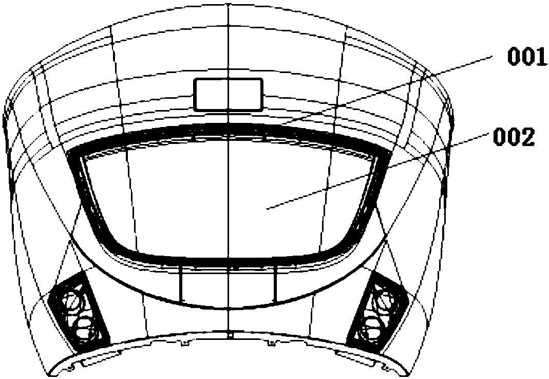
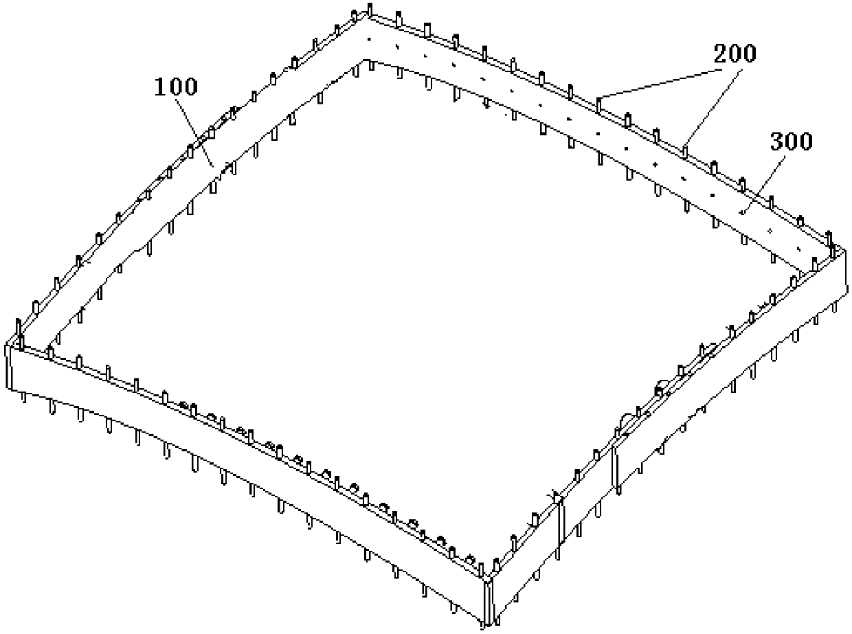
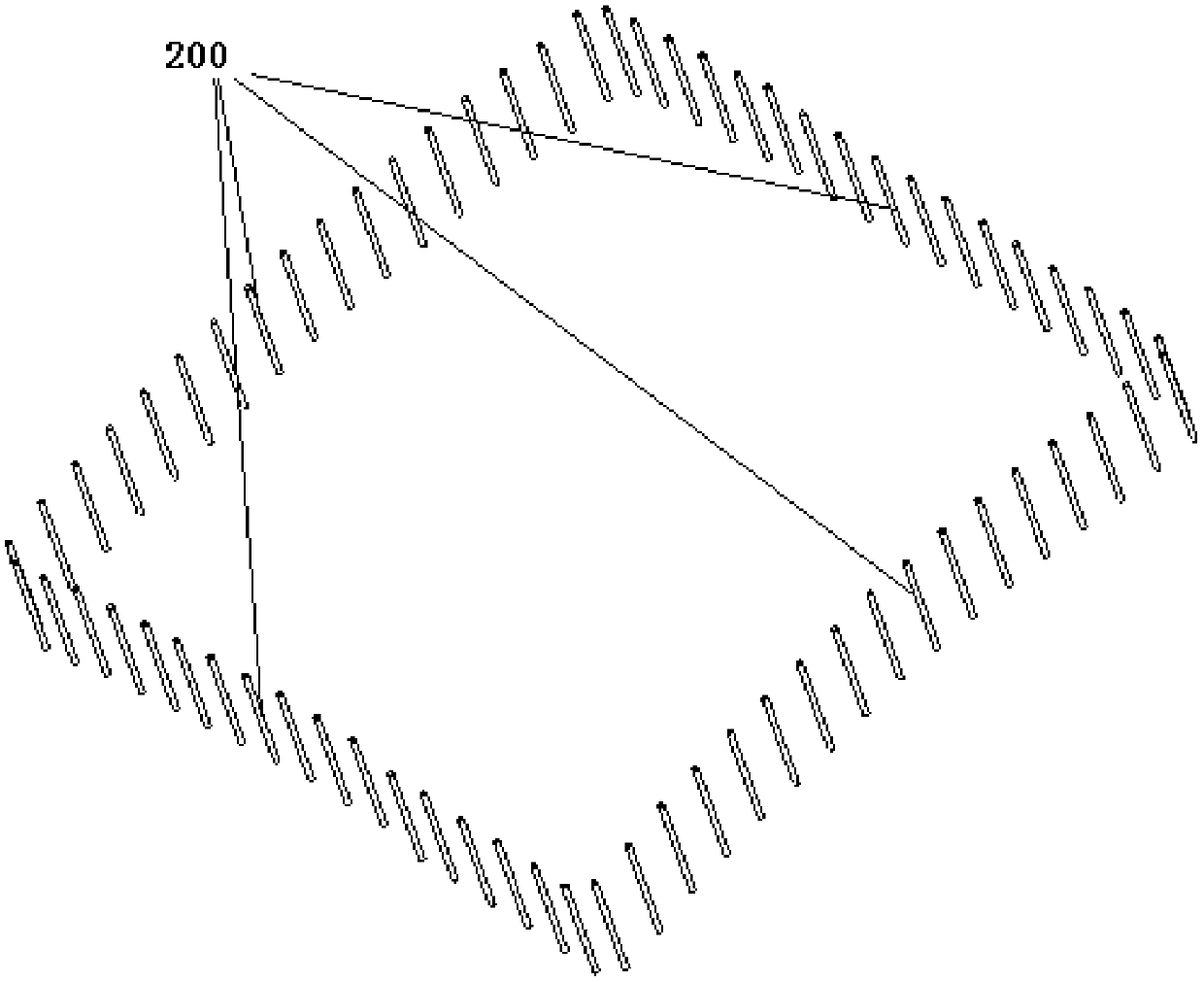
[0038] figure 1 It is a schematic diagram of the assembly of the front windshield and the bonding frame; figure 2 Schematic diagram of the structure of the installation detection device provided in the first embodiment; image 3 It is a schematic diagram of the layout of the positioning pins in the installation detection device provided in the first embodiment.
[0039] Please refer to Figure 1-3 , this embodiment provides an installation detection device for a front windshield glass of a rail vehicle, which can assist the assembly of the front windshield glass 002 and the bonding frame 001, and specifically includes: a frame 100, the frame 100 facing the first side of the bonding frame 001 One surface is an arc surface; positioning pins 200, the positioning pins 200 are multiple, the positioning pins 200 are evenly arranged on the frame 100 along the circumference of the frame 100, and the positioning pins 200 can be along the frame 100 The height direction moves relativ...
Embodiment 2
[0050] Figure 4 It is a schematic structural diagram of the installation detection device provided in the second embodiment.
[0051] Please refer to Figure 4 , and please continue to refer to Figure 1-3 , on the basis of the first embodiment, the structure of the frame 100 will be described in detail in this embodiment. It can be understood that: this embodiment is only an example to illustrate the structure of the frame 100, and the structure of the frame 100 is not limited thereto.
[0052] Further, the frame 100 includes: two first connecting plates 110 oppositely arranged, and a plurality of through holes are arranged on the first connecting plates 110, and part of the positioning pins 200 are arranged in the through holes of the first connecting plates 110. in the hole. The frame 100 also includes: two second connecting plates 120 oppositely arranged, and a plurality of through holes are arranged on the second connecting plates 120, and the rest of the positioning...
Embodiment 3
[0059] Figure 5 A schematic structural diagram of the installation detection device provided in the third embodiment.
[0060] Please refer to Figure 5 , and please continue to refer to Figure 1-4 , on the basis of the second embodiment, this embodiment will describe the structure of the second connecting plate 120 in the frame 100 in detail.
[0061] Further, the second connecting plate 120 includes: at least two connecting sub-plates 121, the connecting sub-plates 121 are provided with long holes 121a; fastening bolts 121b, the fastening bolts 121b can pass through adjacent The long holes 121a on the two connecting sub-boards 121 are used to connect two adjacent connecting sub-boards 121 .
[0062] The long hole 121a can be set at one end of the connecting sub-board 121; the length of the long hole 121a is not specifically limited in this embodiment, and those skilled in the art can set it according to actual needs, as long as the adjustment requirements of the frame 1...
PUM
 Abstract
Description
Claims
Application Information
 - R&D
- Intellectual Property
- Life Sciences
- Materials
- Tech Scout
- Unparalleled Data Quality
- Higher Quality Content
- 60% Fewer Hallucinations
Browse by: Latest US Patents, China's latest patents, Technical Efficacy Thesaurus, Application Domain, Technology Topic, Popular Technical Reports.
© 2025 PatSnap. All rights reserved.Legal|Privacy policy|Modern Slavery Act Transparency Statement|Sitemap|About US| Contact US: help@patsnap.com


