Supercharge Your Innovation With Domain-Expert AI Agents!

A multi-stage cold air cooling device for electronic devices

A technology for electronic devices and heat sinks, which is applied to the field of multi-stage cold air heat sinks for electronic devices, can solve the problems of undetermined radiator structure fans, complicated calculations, and large volume of water-cooled heat sinks, so as to improve heat dissipation effect and facilitate installation. , the effect of improving the degree of automation and controllability

Active Publication Date: 2019-06-14
ANHUI POLYTECHNIC UNIV
View PDF4 Cites 0 Cited by
  • Summary
  • Abstract
  • Description
  • Claims
  • Application Information

AI Technical Summary

Problems solved by technology

[0003] Due to the large heat capacity and density of water, the installation density of devices on the radiator can also be increased, so the water-cooled type has high integration and compact structure. It is more suitable for systems with large total heat generation and a large number of power switching devices, but water-cooled heat dissipation The device is generally bulky, which is obviously not suitable for heat dissipation of electronic devices that require small volume and integration; forced air cooling is reliable in heat dissipation, easy to maintain, and relatively low in cost, so it is widely used in cooling systems for electronic equipment that require heat dissipation , which is also the main form of cooling for high power devices
However, the calculation to determine the forced air cooling parameters in the design is relatively complicated, and the complex interaction between the shell temperature, the radiator and the fan makes it impossible for designers to simply rely on a single factor to determine the structure of the radiator or determine the temperature of the fan.

Method used


Image

  • A multi-stage cold air cooling device for electronic devices
  • A multi-stage cold air cooling device for electronic devices
  • A multi-stage cold air cooling device for electronic devices

Examples


Embodiment

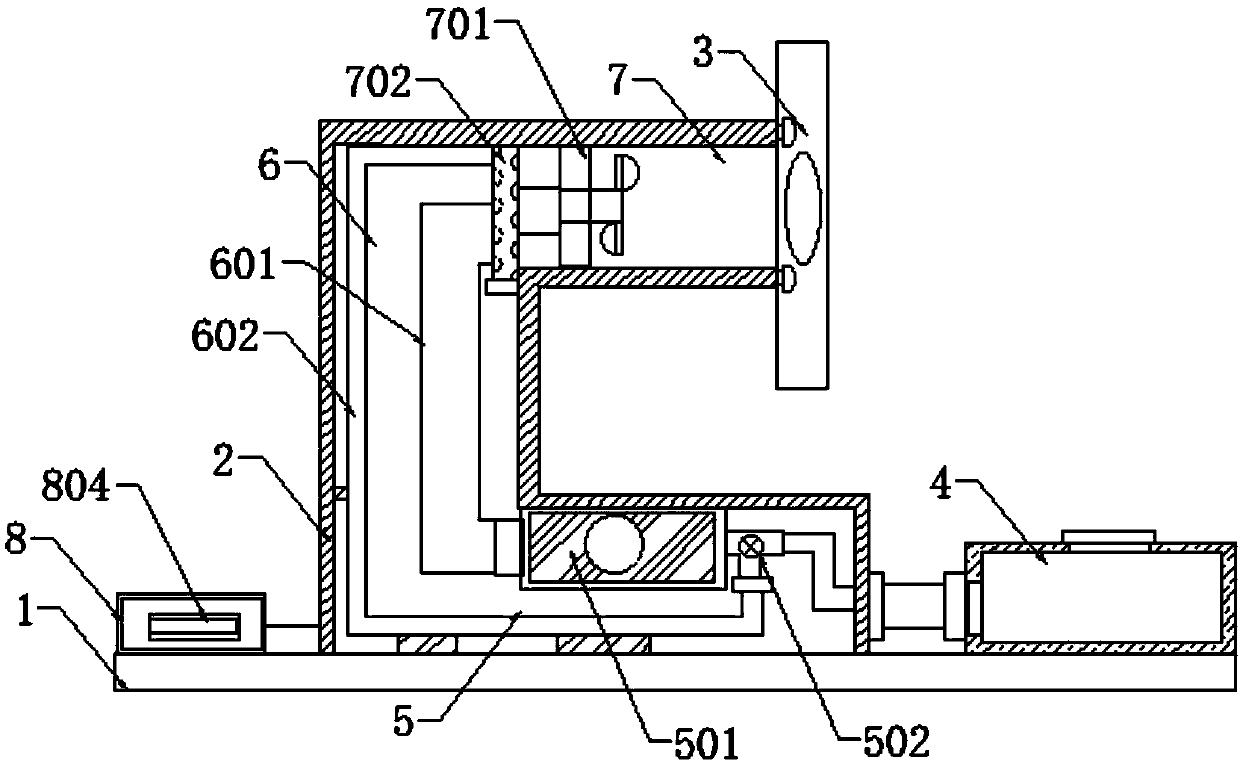
[0027] Such as figure 1 As shown, the present invention provides a multi-stage cold air heat dissipation device for electronic devices, including a heat dissipation base plate 1, the heat dissipation base plate 1 is a cuboid thin plate, and the four corners of the heat dissipation base plate 1 are dug with M5 standard threaded holes, and are fixed on the base plate to be fixed by screws. On the heat dissipation device base, a heat dissipation pipe 2 is welded on the upper surface of the heat dissipation base plate 1, and a heat dissipation fin 3 is installed at the outlet of the upper end of the heat dissipation pipe 2, and the heat dissipation fin 3 is close to the heat dissipation device; the heat dissipation pipe 2 The outlet at the lower end of the outlet is parallel to the heat dissipation bottom plate 1, and a refrigerant box 4 is connected through a pipeline. The refrigerant box 4 is made of heat-insulating material. Rubber sealing plug, refrigerant is stored in the ref...


PUM


Abstract

The invention discloses a multistage cold air radiating apparatus for electronic devices, which includes a radiating bottom plate. A radiating pipe is welded to the upper surface of the radiating bottom plate. A radiating fin is installed at an upper outlet of the radiating pipe, and the radiating fin is arranged close to a device to be radiated. A lower outlet of the radiating pipe is parallel tothe radiating bottom plate, and is connected with a refrigerant box through a pipe. A filling opening is formed through cutting in the top of the refrigerant box. The filling opening is inlaid with arubber sealing plug. Refrigerant is stored in the refrigerant box. The inside of the radiating pipe is segmented by half wind shield plates into three stages of spaces. The transverse pipe at the bottommost of the radiating pipe is a condensing chamber, the vertical pipe is a circulating chamber, and the top transverse pipe is an air cooling chamber. A control panel is also welded onto the radiating bottom plate. A PLC and a rechargeable battery are welded onto the control panel. The control output port of the PLC is connected with a multi-channel electronic switch. The multistage cold air radiating device is small, safe and flexible. By combining a cooling fan and the radiating pipe, a good radiating effect is achieved, the energy consumption is low, and the efficiency is high.

Description

technical field [0001] The invention relates to the field of heat dissipation devices for electronic devices, in particular to a multi-stage cold air heat dissipation device for electronic devices. Background technique [0002] Electronic equipment usually requires high reliability, and excellent heat dissipation is an important guarantee for the reliable operation of electronic equipment. In electronic equipment, the main heat generation is generated by high-power devices, so the heat dissipation of high-power devices is the key to the heat dissipation of the entire electronic equipment. Existing heat dissipation technologies are mainly divided into water-cooled heat dissipation and air-cooled heat dissipation; [0003] Due to the large heat capacity and density of water, the installation density of devices on the radiator can also be increased, so the water-cooled type has high integration and compact structure. It is more suitable for systems with large total heat genera...

Claims


Application Information

Patent Timeline
Patent Type & Authority Patents(China)
IPC IPC(8): H05K7/20
Inventor 王军杨洋
Owner ANHUI POLYTECHNIC UNIV
Features
  • R&D
  • Intellectual Property
  • Life Sciences
  • Materials
  • Tech Scout
  • Unparalleled Data Quality
  • Higher Quality Content
  • 60% Fewer Hallucinations
Learn More