
Automatic detection device for appearance of glass tube

An automatic detection and glass tube technology, used in measuring devices, chemical instruments and methods, cleaning flexible objects, etc., can solve the problems that the surface dust cannot be cleaned, the glass tube cannot be cleaned, and the glass tube is fed too much, etc., to achieve production efficiency. High, multi-functional, avoid the effect of overfeeding

Inactive Publication Date: 2018-01-26
中山市标致电子科技有限公司
View PDF0 Cites 0 Cited by
  • Summary
  • Abstract
  • Description
  • Claims
  • Application Information

AI Technical Summary

Problems solved by technology

[0003] In the prior art, equipment testing requires artificial feeding, and the quantity and time of feeding are artificially controlled, which leads to the problem that the detection speed is too slow, and it is easy to cause too much feeding of the glass tube, causing damage to the glass tube itself, and the existing The equipment cannot clean the glass tube after inspection, which leads to the problem that the dust on the surface of the glass tube cannot be cleaned after leaving the factory, the production efficiency is low, and the scrap rate is high. In summary, the existing equipment can no longer meet people's needs. There is an urgent need for a new type of automatic detection equipment for the appearance of glass tubes to solve the above problems

Method used


Image

  • Automatic detection device for appearance of glass tube
  • Automatic detection device for appearance of glass tube
  • Automatic detection device for appearance of glass tube

Examples


specific Embodiment approach

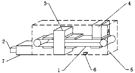
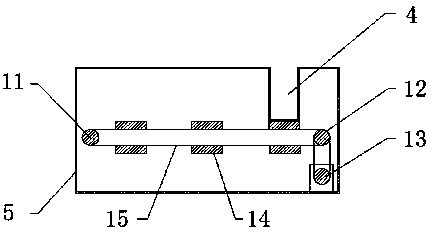
[0025] Specific embodiments: the user connects the present invention with an external power supply, and puts the glass tube to be detected into the feeding chamber 4, the external power supply transmits the electric energy to the storage battery 6 through the wire, and the storage battery 6 stores the electric energy inside, and closes the switch. Connect the internal circuit of the present invention, the storage battery 6 transmits the electric energy to the motor 13 through the electric wire, the electric motor 13 converts the electric energy into mechanical energy, and drives the driving wheel 12 to rotate, the driving wheel 12 utilizes the transmission belt 15 to drive the driven wheel 11 to rotate, and the glass tube moves from the top The material chamber 4 falls on the transmission belt 15 and moves together with the transmission belt 15. When the glass tube moves into the detection chamber 3, the user detects the glass tube. When the lower end surfaces of the feeding ch...


PUM


Abstract

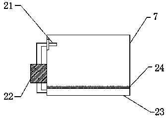
The invention provided an automatic detection device for appearance of a glass tube. The automatic detection device comprises a detection chamber, a feeding chamber, a working chamber, a driven wheel,a driving wheel, a motor, protruding blocks, a transmission belt, a spray head, a water pump and a water collecting tank; and the detection chamber is assembled on the left side of the lower end surface in the working chamber, the feeding chamber is arranged on the right side of the upper end surface in the working chamber, the driving wheel is connected with the driven wheel through the transmission belt, the motor is connected with the driving wheel through a chain, and the protruding blocks are arranged on the surface of the transmission belt. According to the automatic detection device, the feeding detection is integrated through the design, feeding time and quantity can be automatically controlled, so that too much feeding of the glass tube is avoided, and damage to the glass tube isavoided; the lower part of the left end face of the water collecting tank and the spray head are connected with the water pump through water pipes so that dust on the glass tube after delivery can becleaned, production efficiency is improved, and rejection rate is reduced; and the automatic detection device has the advantages that production efficiency is high, operation is convenient, functionsare diversified, and practicability is high.

Description

technical field [0001] The invention is an automatic detection device for the appearance of a glass tube, which belongs to the technical field of glass tube detection equipment. Background technique [0002] The glass tube is a relatively transparent solid substance that forms a continuous network structure during melting, and is a silicate non-metallic material that gradually increases in viscosity and hardens during cooling. Glass tube products are a general term for daily necessities and industrial products processed from glass tubes as the main raw material. Glass tube products are widely used in people's economic life. According to the shape, glass tube products can be divided into glass tube pieces, glass tubes and irregular glass tube bodies. In the production process of glass tubes, we have to check the quality of glass tubes. detection. [0003] In the prior art, equipment testing requires artificial feeding, and the quantity and time of feeding are artificially c...

Claims


Application Information

Patent Timeline
Patent Type & Authority Applications(China)
IPC IPC(8): B08B3/02B08B3/14B08B11/00G01N33/00G01N35/10
Inventor 赵加强王朋朋甘国国
Owner 中山市标致电子科技有限公司
Learn More