Electric vehicle regenerative braking force distribution method

A technology of regenerative braking force and electric vehicles, applied in electric vehicles, electric braking systems, vehicle components, etc., can solve the problems of occupant discomfort, low braking energy recovery rate, low proportion of regenerative braking force, etc.

Active Publication Date: 2019-12-06
CH AUTO TECH CORP CO LTD
View PDF5 Cites 0 Cited by
  • Summary
  • Abstract
  • Description
  • Claims
  • Application Information

AI Technical Summary

Problems solved by technology

[0003] For the regenerative braking system of electric vehicles, the energy recovery rate and occupant comfort are important evaluation indicators for evaluating the braking energy recovery system. At present, the braking force distribution and energy recovery strategies of the regenerative braking system of pure electric vehicles are generally divided into series Two types: series regenerative braking system, when the driver does not operate the brake pedal or lightly steps on the brake pedal, the motor can generate regenerative braking force to decelerate the vehicle. This regenerative braking method can achieve higher However, the frequent deceleration caused by the regenerative braking force in actual driving will make the occupants feel uncomfortable and reduce the comfort of the ride; while the parallel regenerative braking system, only when the driver operates the brake Regenerative braking force is generated only when there is a subjective demand for braking on the pedal, that is, the total braking force of an electric vehicle is generated simultaneously by the traditional mechanical braking force and the regenerative braking force generated by the motor. The braking deceleration process is the same as the driving The driver's subjective needs are consistent, and the ride comfort is better, but because the regenerative braking force accounts for a relatively low proportion of the total braking force, the braking energy recovery rate is low

Method used


Image

  • Electric vehicle regenerative braking force distribution method
  • Electric vehicle regenerative braking force distribution method
  • Electric vehicle regenerative braking force distribution method

Examples


Embodiment Construction

[0047] In order to further explain the technical means and effects of the present invention to achieve the intended purpose of the invention, the specific implementation methods, methods, Structure, characteristic and effect thereof are as follows in detail. In the following description, different "one embodiment" or "embodiment" do not necessarily refer to the same embodiment. Furthermore, the particular features, structures, or characteristics of one or more embodiments may be combined in any suitable manner.

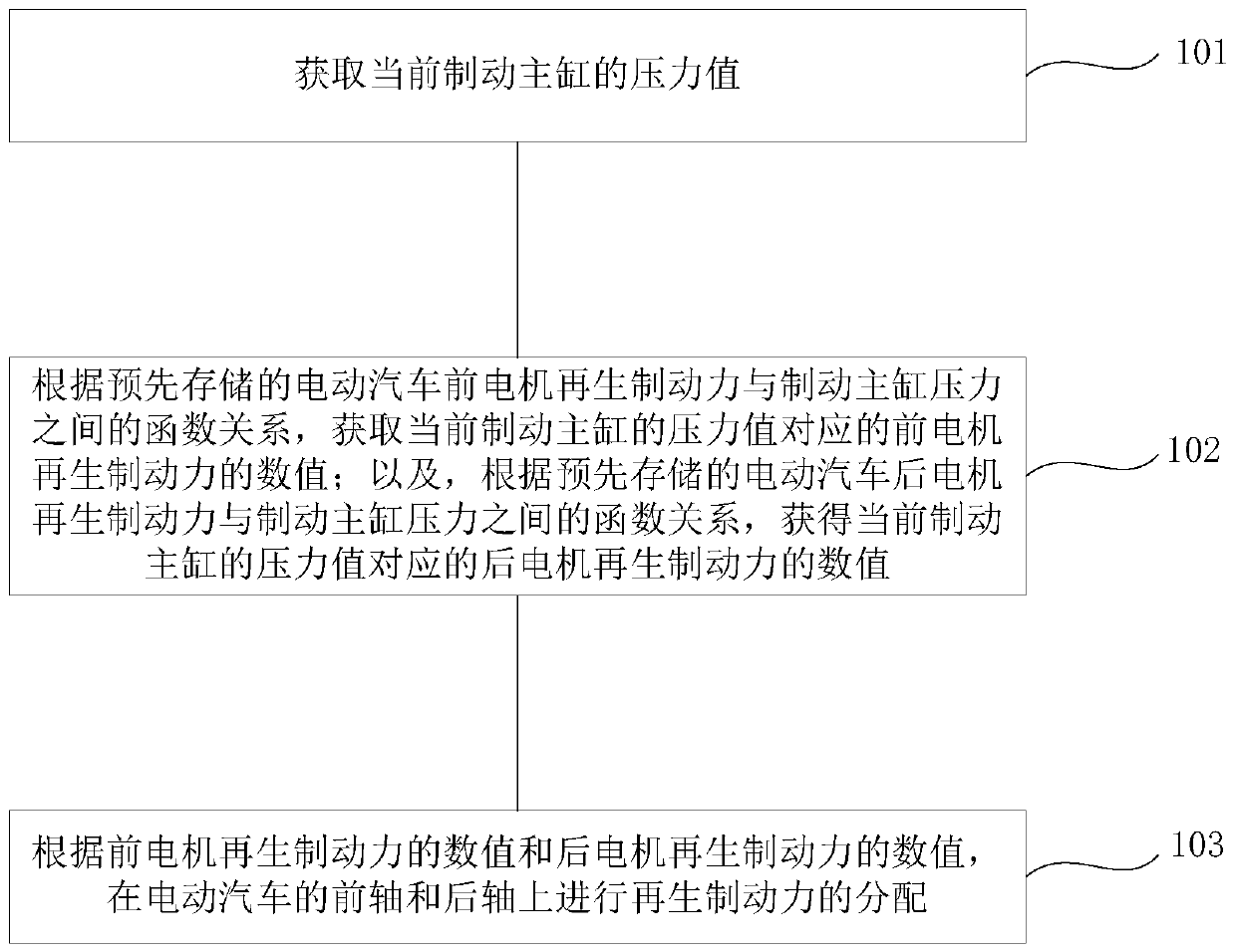
[0048] Such as figure 1 As shown, the embodiment of the present invention proposes a regenerative braking force distribution method for electric vehicles suitable for dual-motor independently driven two-axis electric vehicles, which includes:

[0049] 101. Obtain the current pressure value of the brake master cylinder.

[0050] Specifically, the pressure value of the brake master cylinder can be read through the detection component in the brake system of the electr...


PUM


Abstract

The invention relates to a regenerative braking force distribution method for an electric vehicle, and relates to the technical field of automobile industry. The main technical scheme includes the steps of acquiring a pressure value of a current brake master cylinder; acquiring, according to a pre-stored function relationship between the regenerative braking force of a front motor of the electricvehicle and the brake master cylinder pressure, a value of the corresponding regenerative braking force of the front motor to the pressure value of the current brake master cylinder; acquiring, according to a pre-stored function relationship between the regenerative braking force of a rear motor of the electric vehicle and the brake master cylinder pressure, a value of the corresponding regenerative braking force of the rear motor to the pressure value of the current brake master cylinder; and distributing a regenerative braking force on a front axle and a rear axle of the electric vehicle based on the value of the regenerative braking force of the front motor and the value of the regenerative braking force of the rear motor. The method achieves the rational distribution of the regenerative braking force of the front motor and the regenerative braking force of the rear motor.

Description

technical field [0001] The invention relates to the technical field of the automobile industry, in particular to a method for distributing regenerative braking force of an electric vehicle. Background technique [0002] The regenerative braking of electric vehicles is a braking method that uses the electrical braking of the motor to generate reverse torque to slow down or stop the vehicle. Then, the mechanical energy of the car is converted into electric energy to charge the battery through the reverse freewheeling diode of the inverter, and at the same time, the mechanical energy of the car is consumed to realize the braking of the car. [0003] For the regenerative braking system of electric vehicles, the energy recovery rate and occupant comfort are important evaluation indicators for evaluating the braking energy recovery system. At present, the regenerative braking system of pure electric vehicles generally divides the braking force distribution and energy recovery stra...

Claims


Application Information

Patent Timeline
Patent Type & Authority Patents(China)
IPC IPC(8): B60L7/18
Inventor 陆群赵森
Owner CH AUTO TECH CORP CO LTD
Why Eureka
Try Eureka