Jig plate feeding and discharging equipment

A jig plate and feeding technology, which is applied in the stacking of objects, destacking, transportation and packaging of objects, etc., can solve the problems of single function and poor versatility, and achieve small size, strong practicability, and material loading. And the effect of improving the efficiency of receiving

Pending Publication Date: 2018-01-26
GUANGDONG LXD ROBOTICS CO LTD
View PDF6 Cites 14 Cited by
  • Summary
  • Abstract
  • Description
  • Claims
  • Application Information

AI Technical Summary

Problems solved by technology

This structure can only realize the feeding function of the material, the function i

Method used


Image

  • Jig plate feeding and discharging equipment
  • Jig plate feeding and discharging equipment
  • Jig plate feeding and discharging equipment

Examples


Embodiment Construction

[0023] The present invention will be further described below in conjunction with the accompanying drawings and embodiments.

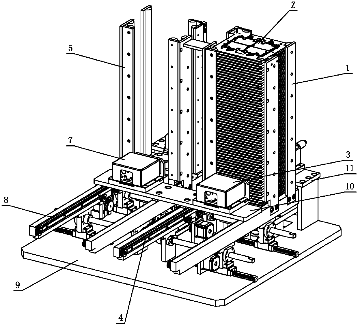
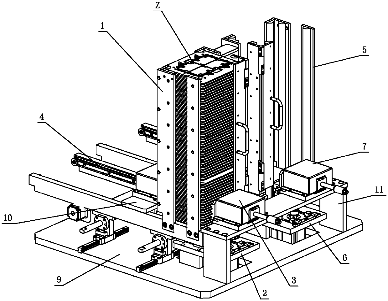
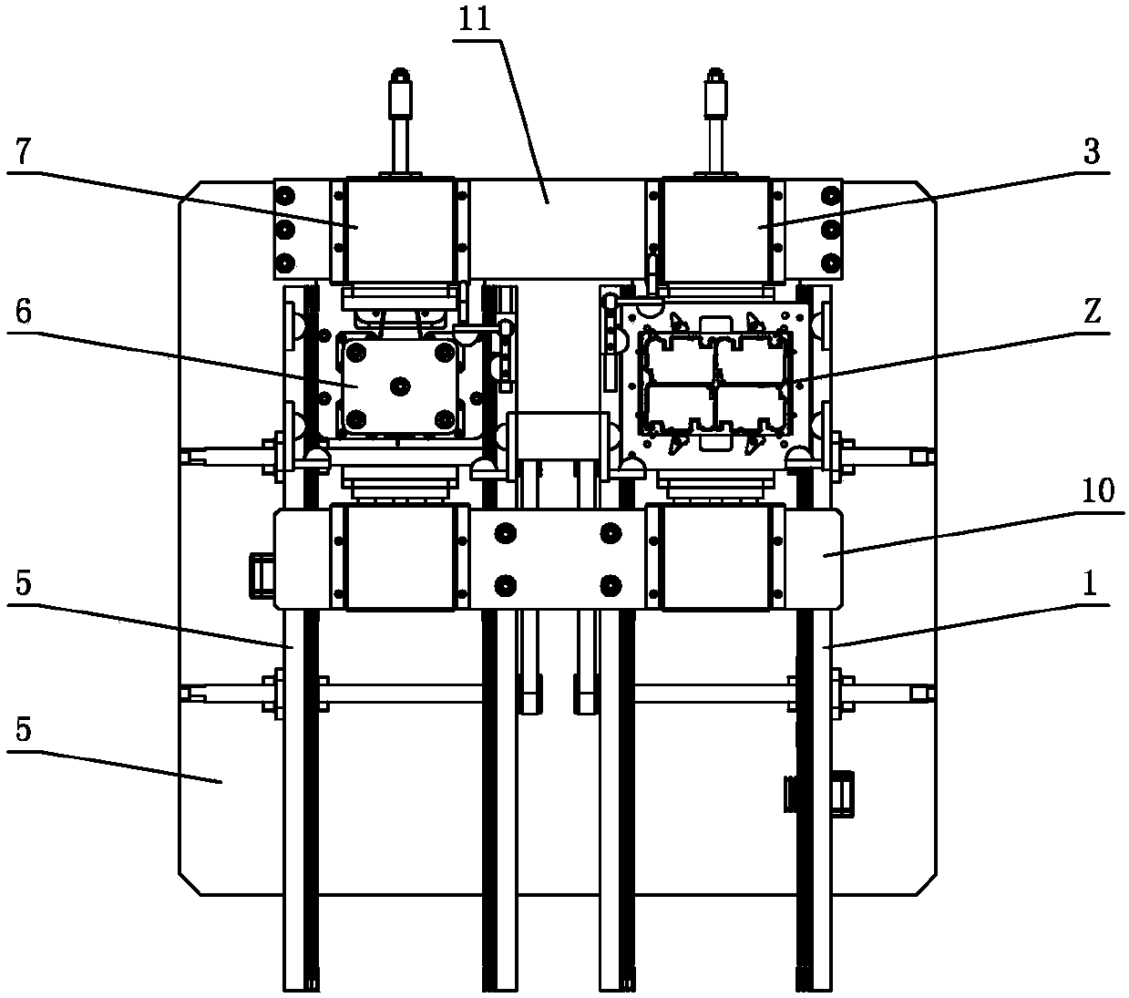
[0024] see Figure 1-Figure 13 , the jig plate loading and unloading equipment, including the feeding push system and the receiving push system; The direction is opposite to the pushing direction of the jig board Z on the material receiving and pushing system. The jig board Z realizes feeding on the feeding and pushing system, and the jig board Z realizes receiving on the receiving and pushing system; the feeding and pushing system The structure is basically the same as that of the material receiving and pushing system, and they are arranged symmetrically with each other.

[0025]The feeding push system includes a feeding limit mechanism 1, a feeding lifting mechanism 2, a feeding supporting mechanism 3 and a feeding conveying mechanism 4; The stacking area and the feeding and conveying area used to transport the jig plate Z, the intersection of the l...


PUM


Abstract

Jig plate feeding and discharging equipment comprises a feeding pushing system and a material receiving pushing system. The feeding pushing system comprises a feeding limiting mechanism, a feeding lifting mechanism, a feeding bearing mechanism and a feeding conveying mechanism. The feeding limiting mechanism is provided with a feeding stacking area and a feeding conveying area. The feeding liftingmechanism is arranged on a feeding station. The feeding bearing mechanism is arranged on the outer side of the feeding stacking area. The feeding conveying mechanism is arranged on the feeding conveying area. The material receiving pushing system comprises a material receiving limiting mechanism, a material receiving lifting mechanism, a material receiving bearing mechanism and a material receiving conveying mechanism. The material receiving limiting mechanism is provided with a material receiving stacking area and a material receiving conveying area. The material receiving lifting mechanismis arranged on a material receiving station. The material receiving bearing mechanism is arranged on the outer side of the material receiving stacking area. The material receiving conveying mechanismis arranged in the material receiving conveying area. The jig plate feeding and discharging equipment is simple and reasonable in structure, small in occupied space, capable of achieving jig plate feeding or discharging at any time without shutdown, the automation degree is high, the work efficiency is high, the jig plate feeding and discharging equipment can adapt to different types of jig plates, and universality is high.

Description

technical field [0001] The invention relates to an automatic loading and unloading equipment, in particular to a jig plate unloading equipment, which can be used for loading or receiving operations of SMT patch jigs, dispensing upper jig plates and dispensing lower jig plates , to provide a solution for the loading and unloading of fixture boards. Background technique [0002] SMT loading machines are widely used in the electronics industry, but traditional loading machines are huge in size, have no connection mechanism and need to place the jig board in the transfer frame to realize automatic loading, which is not conducive to electronic factories with limited space. Integrate applications with robots. Chinese Patent Document No. CN103896057B disclosed a fully automatic unloading mechanism on January 20, 2016, specifically disclosing: including a frame, a loading frame, a blocking and distributing mechanism, a feeding mechanism, a blanking mechanism, a lifting mechanism an...

Claims


Application Information

Patent Timeline
IPC IPC(8): B65G59/06B65G57/30
CPCY02P70/50
Inventor 覃军富黄学志曾磊胡尕磊
Owner GUANGDONG LXD ROBOTICS CO LTD
Why Eureka
Try Eureka