
Curtain wall keel connecting structure for final installation of horizontal keels

A technology for connecting structures and horizontal keels, applied to walls, building components, building structures, etc., can solve the problems of poor connection strength between horizontal keels and vertical keels, reduce the service life of curtain walls, and affect the installation of curtain wall panels, etc., to achieve simplicity and refinement Good performance and service life, anti-rust performance, simple structure

Pending Publication Date: 2018-01-26
HUNAN GOLDWELL NEW MATERIALS TECH CO LTD
View PDF9 Cites 0 Cited by
  • Summary
  • Abstract
  • Description
  • Claims
  • Application Information

AI Technical Summary

Problems solved by technology

[0003] However, the existing curtain wall technology for post-installation of transverse keel is not mature enough, and there are many defects as follows:
[0004] 1. The connection strength between the horizontal keel and the vertical keel is poor, and even cannot meet the strength requirements of the curtain wall, especially when the connection stress points of the horizontal keel are concentrated on the side wall on one side, the shear and torsion resistance of the horizontal keel will be greatly reduced. Cause connection strength and stability to decline, and even fail to meet the strength requirements of the curtain wall
[0005] 2. The connectors and screws between the keels are difficult to hide, and most of the connectors and screws are exposed, which not only affects the installation of the curtain wall panels, but also makes the appearance of the curtain wall after installation not simple and exquisite, and is easy to rust, reducing the service life of the curtain wall

Method used


Image

  • Curtain wall keel connecting structure for final installation of horizontal keels
  • Curtain wall keel connecting structure for final installation of horizontal keels
  • Curtain wall keel connecting structure for final installation of horizontal keels

Examples


Embodiment 1

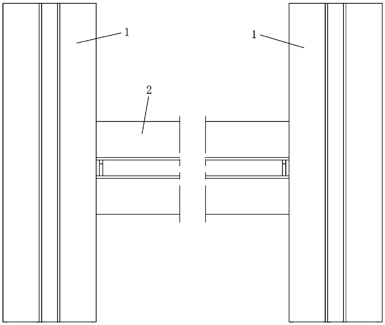
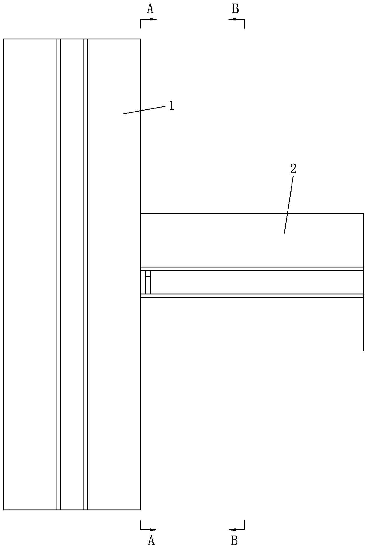
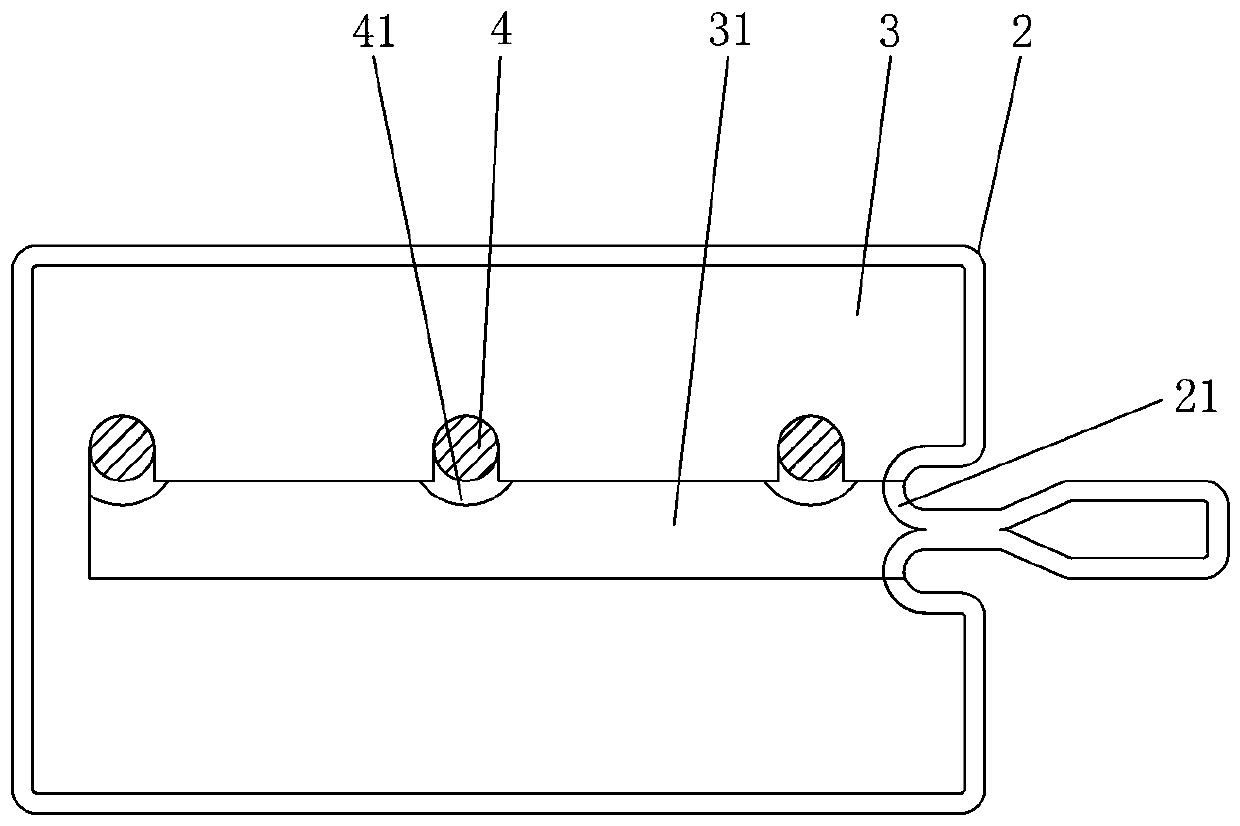
[0039] Such as Figure 1 to Figure 5 As shown, the curtain wall keel connection structure for post-installation of the horizontal keel in this embodiment includes two vertical keels 1 and a horizontal keel 2 installed between the two vertical keels 1, and the horizontal keel 2 is a circumferentially closed tubular profile , each vertical keel 1 is connected with a shear connection assembly located in the inner cavity of the horizontal keel 2 and supports the horizontal keel 2, the shear connection assembly includes an inner connecting piece 3 fixedly installed in the inner cavity of the horizontal keel 2, and the inner connecting piece 3 An open slot 31 with an open end is provided, and more than one supporting part 4 that can be inserted into the open slot 31 from the opening of the open slot 31 is installed on the vertical keel 1, and each supporting part 4 is located in the open slot 31 and holds the Connector 3, the opening groove 31 is provided with a card sleeve on the s...

Embodiment 2

[0047] The curtain wall keel connection structure used for the post-installation of the transverse keel in this embodiment is basically the same as in Embodiment 1, the main difference is that, as Image 6 with Figure 7 As shown, in this embodiment, only one supporting part 4 is installed on the vertical keel 1, and the top end of the supporting part 4 is provided with a supporting surface that contacts and cooperates with the internal connecting part 3 and supports the internal connecting part 3. The contact surface between the holding surface and the inner connector 3 is a horizontal plane, so as to improve the stability of supporting the transverse keel 2 .

Embodiment 3

[0049] The curtain wall keel connection structure used for the post-installation of the transverse keel in this embodiment is basically the same as in Embodiment 1, the main difference is that, as Figure 8 with Figure 9 As shown, in this embodiment, the anti-retraction bayonet 311 is a circular opening communicating with the opening groove 31, and the supporting member 4 is a bar that is inserted into the circular opening from the opening groove 31 and prevents the inner connecting member 3 from moving up and down and back and forth. Shaped parts, the supporting part 4 simultaneously limits the freedom of the transverse keel 2 in the up and down and front and rear directions, which can improve the stability of the transverse keel 2 after installation.

[0050] In this embodiment, a connection assembly connected to the vertical keel 1 is connected to the outside of the horizontal keel 2 to strengthen the connection and prevent the relative rotation of the supporting part 4 an...


PUM


Abstract

The invention relates to a curtain wall keel connecting structure for final installation of a horizontal keel. The curtain wall keel connecting structure comprises two vertical keels and a horizontalkeel which is finally installed between the two vertical keels, wherein the horizontal keel is a tubular section closed in the circumferential direction, and at least one vertical keel is connected with a shear-resisting connecting assembly which is positioned in an inner cavity of the horizontal keel and supports the horizontal keel; the shear-resisting connecting assembly comprises an inner connecting piece fixedly arranged in the inner cavity of the horizontal keel, and the inner connecting piece is provided with an opening groove with an opening end; the vertical keel is provided with onesupporting component or more which can be placed in the opening groove through the opening of the opening groove, and each supporting component is positioned in the opening groove and supports the inner connecting piece; a retaining bayonet which is sleeved on the supporting component in a clamping way to stop the supporting component from being pulled away from the opening groove is formed in theopening groove, and a notch capable of allowing the supporting component to enter the opening groove is formed in the end part of the horizontal keel. The curtain wall keel connecting structure has the advantages of simple structure, easy fabrication, low cost, simple and convenient installation, good connection strength and firmness and the like.

Description

technical field [0001] The invention relates to the technical field of construction engineering, in particular to a curtain wall keel connection structure for post-installation of transverse keels. Background technique [0002] At present, the connection of horizontal and vertical keels in curtain walls on the market is mainly in two ways: splicing and welding. Among them, splicing is divided into two types: one is to install in sequence by unit, that is, install the first vertical keel first, and then install horizontal keels and vertical keels alternately on the side of the first vertical keel until the entire curtain wall is completed. The other is the post-installation method of the horizontal keel, that is, first install all the vertical keels of the curtain wall according to the set interval size, and then install the horizontal keel between the adjacent vertical keels. The disadvantage of the above-mentioned former installation method is that once the keel needs to b...

Claims


Application Information

Patent Timeline
Patent Type & Authority Applications(China)
IPC IPC(8): E04B2/96
Inventor 李杰谢斌泉其他发明人请求不公开姓名
Owner HUNAN GOLDWELL NEW MATERIALS TECH CO LTD
Learn More