
Tight oil energy supplying method of alternating displacement and imbibition oil displacement between horizontal well sections

A horizontal well section and energy replenishment technology, which is applied in earthwork drilling, wellbore/well components, and production fluids, etc., can solve the problems of difficult energy replenishment in development, slow lateral displacement of water flooding, etc., and achieve the goal of overcoming development energy Complement the effect of difficulty

Active Publication Date: 2018-01-26
PETROCHINA CO LTD
View PDF5 Cites 16 Cited by
  • Summary
  • Abstract
  • Description
  • Claims
  • Application Information

AI Technical Summary

Problems solved by technology

[0007] The purpose of the present invention is to overcome the problem of difficult energy replenishment in the development of horizontal wells in tight oil reservoirs at present, and provide a tight oil energy replenishment method for interlaced displacement and imbibition flooding between horizontal well sections, which has a large start-up pressure gradient for tight oil On the basis of researches on the characteristics of the reservoir, the seepage characteristics of displacement and imbibition in the development of water injection oil recovery, and the development characteristics of the slow lateral displacement of water flooding, combined with the distribution characteristics of artificial fracturing and the effect of imbibition flooding The results of the research on the relationship with the fracture network and other achievements have proposed a systematic energy supplement method to reduce the decline of tight oil and increase the cumulative oil production from the perspective of well pattern deployment, injection mode and water injection technology policy.

Method used


Image

  • Tight oil energy supplying method of alternating displacement and imbibition oil displacement between horizontal well sections
  • Tight oil energy supplying method of alternating displacement and imbibition oil displacement between horizontal well sections
  • Tight oil energy supplying method of alternating displacement and imbibition oil displacement between horizontal well sections

Examples


Embodiment 1

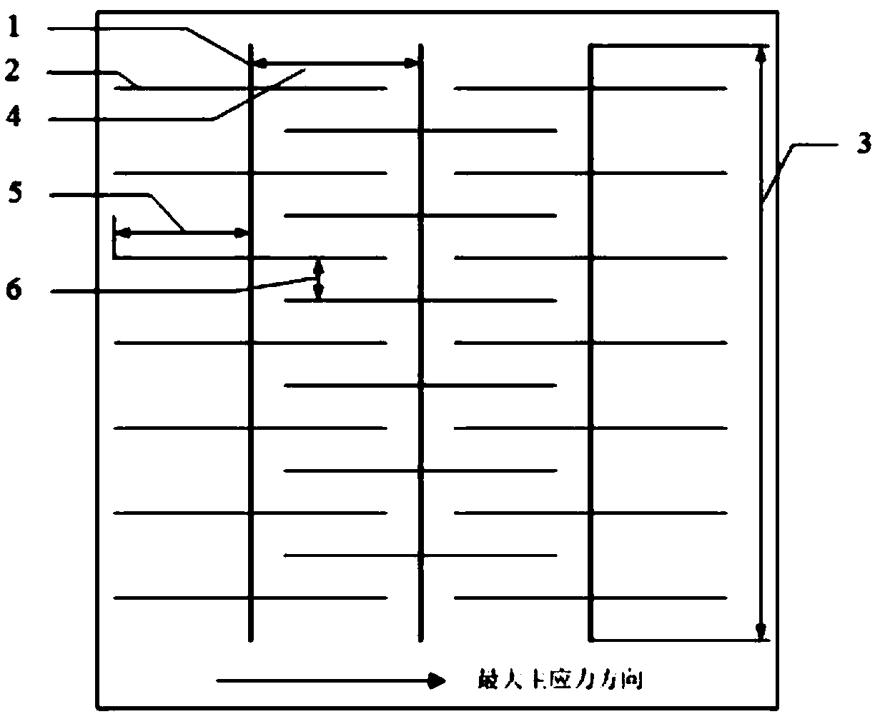
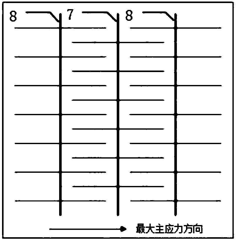
[0065] In order to overcome the problem of difficult energy replenishment in the development of horizontal wells in tight oil reservoirs, this embodiment provides a tight oil energy replenishment method for interlaced displacement and imbibition displacement between horizontal well intervals, see figure 1 and figure 2 , including the following steps:

[0066] Step 1) selecting and classifying the reservoirs, dividing the reservoirs into grades I, II and III, and deploying and exploiting the horizontal well 1 sequentially according to the reservoirs of grades I, II and III;

[0067] Step 2) Deployment of horizontal wells 1: a plurality of horizontal wells 1 are sequentially arranged on the I, II, and III level reservoirs, and then a plurality of artificial fractures 2 are fractured in the vertical direction of each horizontal well 1, and the horizontal wells 1 two The lengths of the artificial fractures 2 on the side are equal. The setting of the horizontal well 1 includes th...

Embodiment 2

[0077] On the basis of Example 1, this example provides a tight oil energy replenishment method for interlaced displacement and imbibition flooding between horizontal well sections. Further, the selection of reservoirs in step 1) includes the following two point:

[0078] ① On the plane, the classification coefficient is established by four parameters of reservoir porosity, movable fluid saturation, mainstream throat radius and starting pressure gradient, and the reservoir is divided into grades I, II and III according to the classification coefficient and permeability;

[0079] The reservoir porosity of the first-level reservoir is 6.7-8.0%, the movable fluid saturation is 53-62%, the mainstream throat radius is 1.3-2.5 μm, the starting pressure gradient is 0.05-0.2 MPa / m, and the classification coefficient is 1.5-2.5 μm. 3.5, the permeability is 0.5~1.0mD;

[0080] The reservoir porosity of the second-level reservoir is 5.6-8.0%, the movable fluid saturation is 42-55%, the ...

Embodiment 3

[0084]On the basis of Example 1, this example provides a tight oil energy replenishment method for interlaced displacement and imbibition flooding between horizontal well sections. Further, the direction of the horizontal well in step 2) is perpendicular to The direction of the maximum principal stress, the length 3 of the horizontal section does not exceed 1500m, and the well spacing 4 is the half length of the artificial fracture 5.

[0085] According to imaging logging and downhole microseismic test results, the maximum principal stress direction is generally NE75°, and the horizontal well direction is perpendicular to the maximum principal stress direction to ensure the best fracturing effect for horizontal wells in the fracturing process and improve Single well production. The design of the length of the horizontal section on the well pattern deployment is not only affected by the distribution characteristics of the continuity of the oil layer, but also the maturity of th...


PUM

PropertyMeasurementUnit
Permeabilityaaaaaaaaaa

Abstract

The invention provides a tight oil energy supplying method of alternating displacement and imbibition oil displacement between horizontal well sections. The method comprises the steps that reservoirsare selected and classified, the reservoirs are classified into level I, level II and level III, and deploy and exploit of horizontal wells are implemented in sequence according to the I, II and III level reservoirs. According to the novel method, water injection well and oil well classification, small well spacing and small section spacing are optimized, segmented lateral displacement and imbibition oil displacement are combined, and rapid water injection energy supplying of tight oil horizontal wells and the same rows of continuous interval wells is achieved; the difficult problem that pressure between artificial cracks cannot be improved effectively is solved; the problem that energy sullying of current tight oil reservoir horizontal well developing is difficult is overcome; and the effect of imbibition oil displacement is achieved to the greatest extent.

Description

technical field [0001] The invention relates to the field of oil field development, in particular to a method for supplementing energy in the development of tight oil horizontal wells, and is a development method for improving development benefits by decreasing the decline of tight oil and increasing and accumulating production. Background technique [0002] With the increasingly prominent contradiction between world oil supply and demand and the gradual shortage of high-quality oil resources, the development of tight oil resources has become a new topic for the development of my country's oil industry. By the end of 2016, the amount of low-permeability-tight oil resources reached 4495×10 8 t, accounting for 48% of the world's total oil resources. At present, horizontal well + volumetric fracturing natural energy is a common way to develop this type of reservoir. However, whether it is a foreign high-pressure tight oil reservoir (formation pressure coefficient between 1.2-1...

Claims


Application Information

Patent Timeline
IPC IPC(8): E21B43/14E21B43/26E21B43/30E21B43/20E21B43/12
Inventor 樊建明李忠兴屈雪峰刘丽丽王冲成良丙薛婷
Owner PETROCHINA CO LTD
Learn More