Gas boost pump and crossover in inverted shroud

a gas boost pump and crossover technology, applied in the field of shrouds, can solve the problems of choking the gas flow, difficult to keep the necessary fluid level over the pump, and the buoyancy force of the gas bubble not acting in the optimum direction, so as to increase the gas handling capacity, increase the gas separation, and increase the production

Active Publication Date: 2011-07-07
BAKER HUGHES INC
View PDF34 Cites 37 Cited by
  • Summary
  • Abstract
  • Description
  • Claims
  • Application Information

AI Technical Summary

Benefits of technology

[0007]The invention is simple and provides enhanced gas separation and increased gas handling capability for high flow or low flow gas well dewatering applications, including vertical wells, horizontal wells, slant wells. This inventio

Problems solved by technology

In horizontal gas wells, however, the gas bubble buoyancy forces are not acting in the optimum direction for moving gas out of the well bore.
Because a significant leng

Method used


Image

  • Gas boost pump and crossover in inverted shroud
  • Gas boost pump and crossover in inverted shroud
  • Gas boost pump and crossover in inverted shroud

Examples


Embodiment Construction

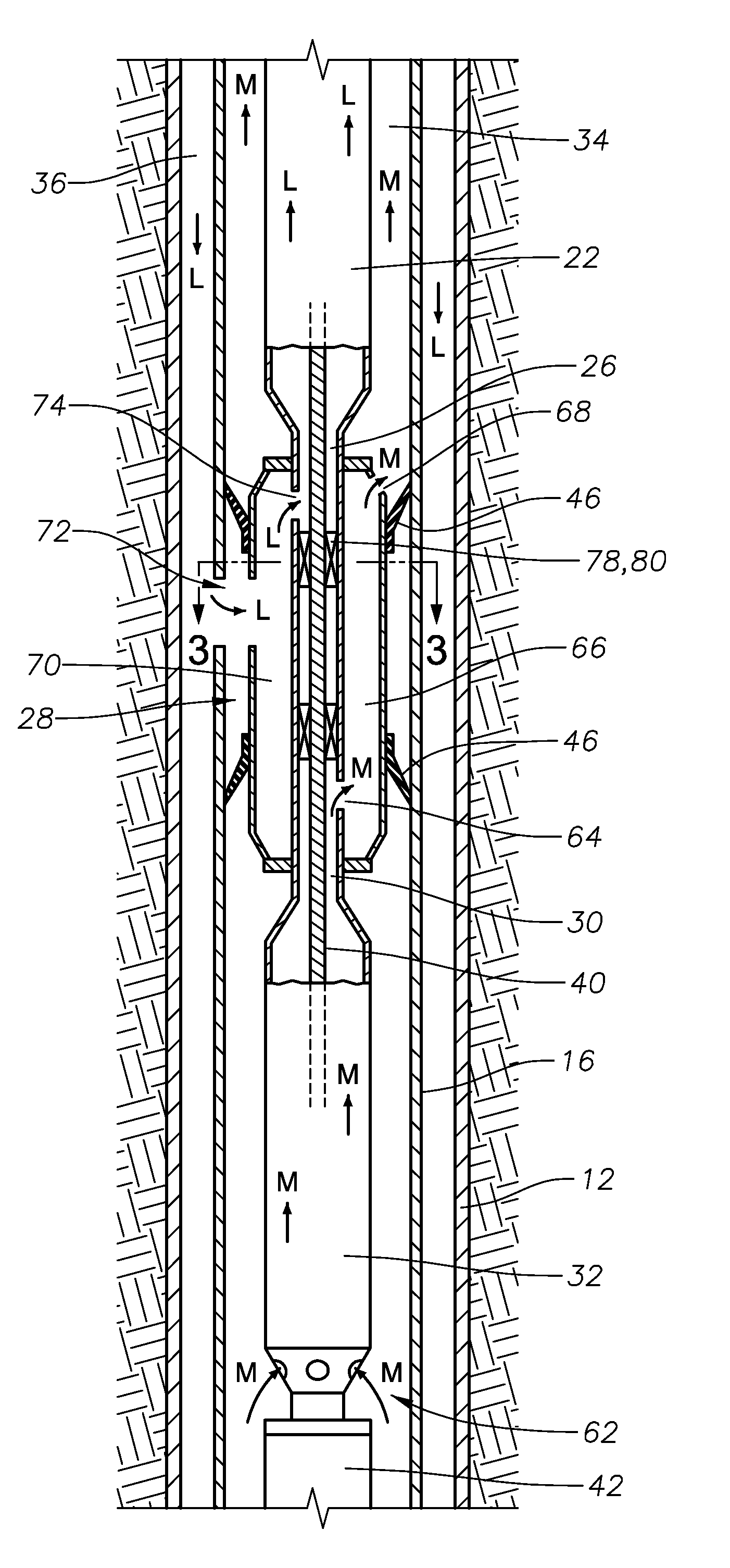
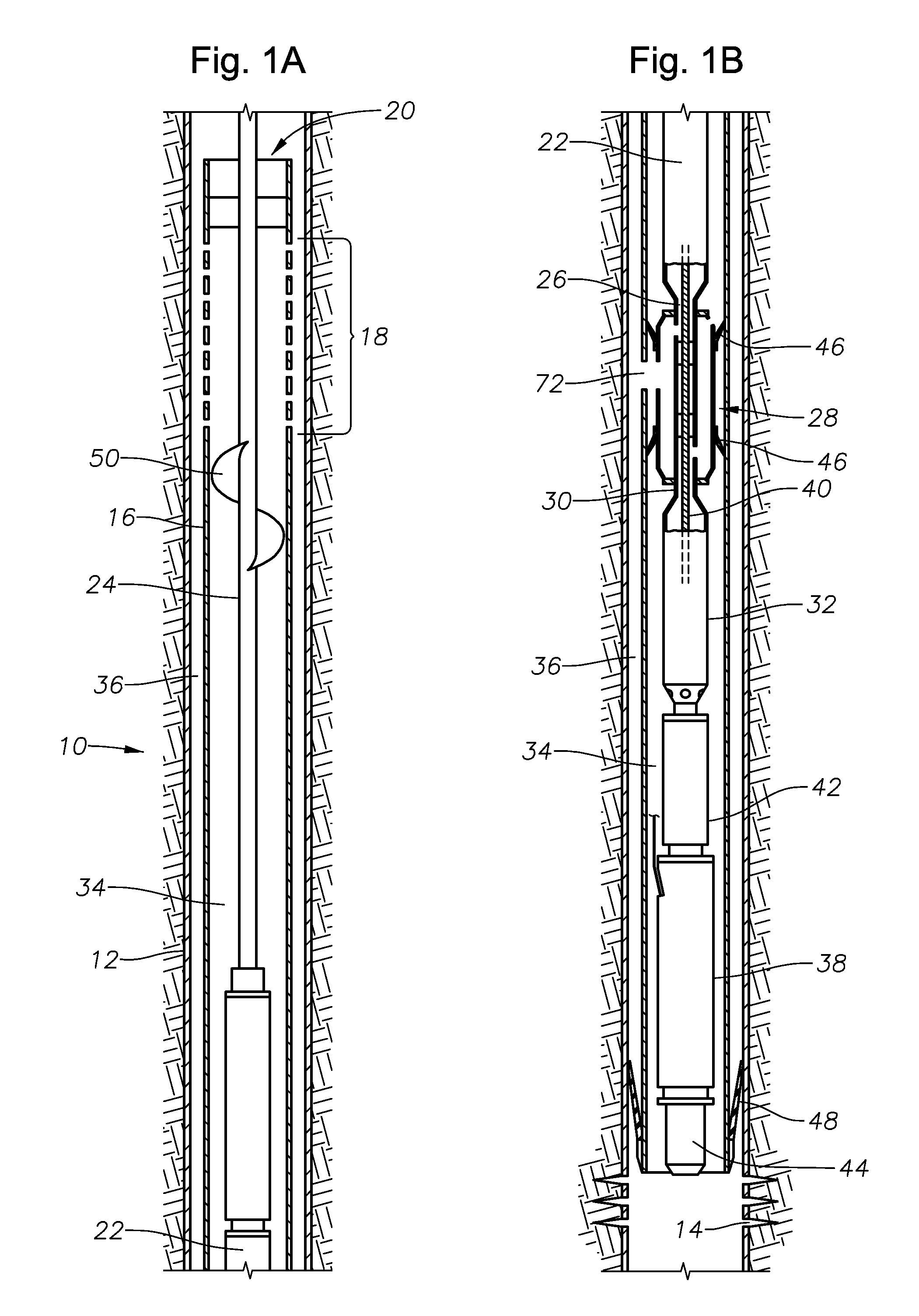
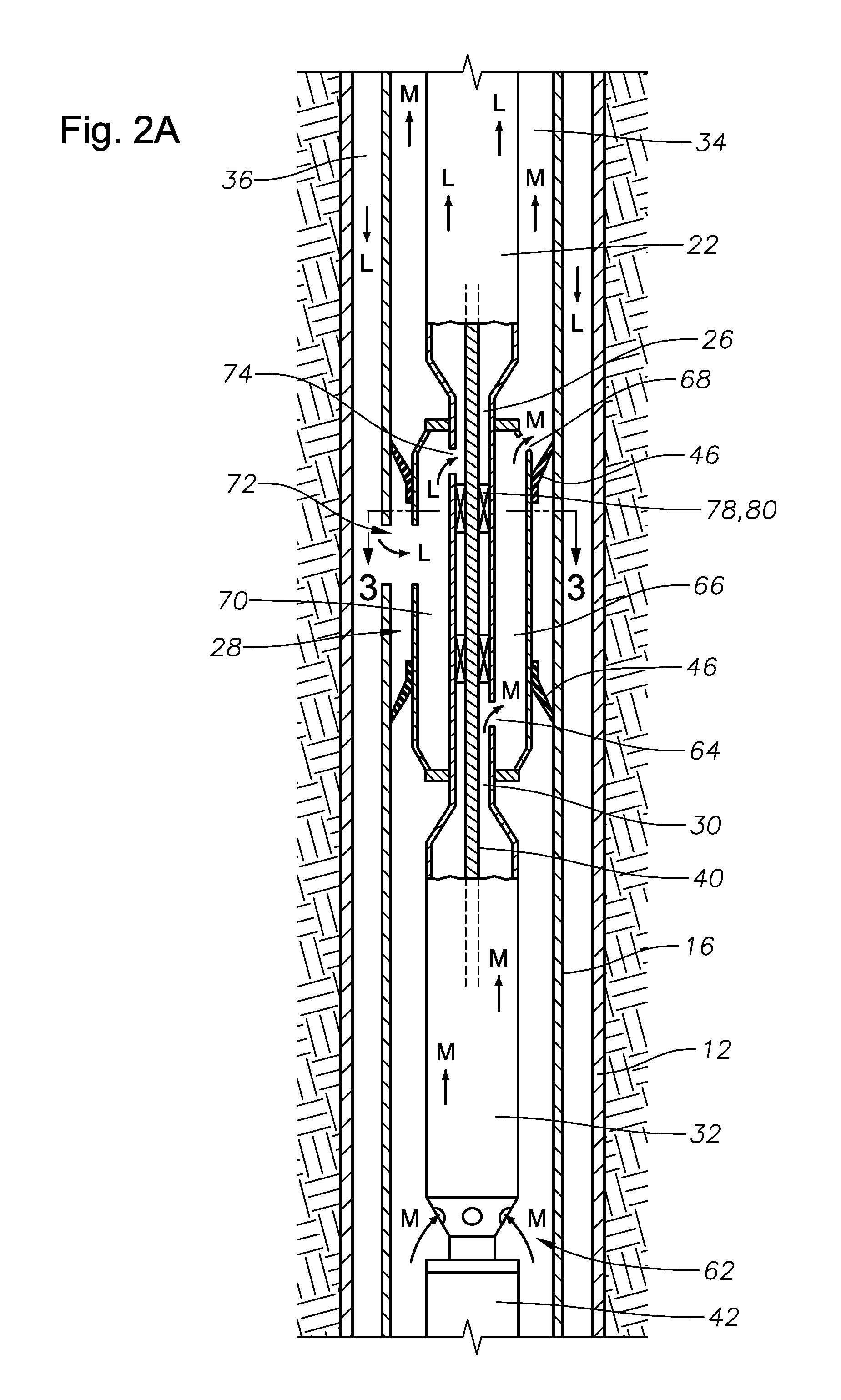
[0011]Referring to FIG. 1, an embodiment of a dewatering apparatus 10 is shown located within the casing 12 of a well having perforations 14 to allow fluid flow from the formation. The dewatering apparatus 10 includes an inverted shroud 16 that may have a separating device or perforated section 18 approximately located at an open top end 20. A lift pump 22 for pumping fluid to the surface via a production tubing string 24 has an intake 26 that may be connected to a downstream end of a crossover assembly 28. The lift pump 22 could comprise multiple stages. A discharge end 30 of a booster pump 32 connects to an upstream end of the crossover assembly 28 to pump a mixed fluid flow of liquid and gas up an inner annulus 34 that is defined by the outer diameter of the lift pump 22 and the inner diameter of the shroud 16. An outer annulus 36 is defined by outer diameter of the shroud 16 and the inner diameter of the casing 12. The booster pump 32 may have stages for gas handling and impelle...


PUM


Abstract

An above-motor mixed flow booster pump combined with a fluid crossover that directs up into the inside of an inverted shroud to allow enhanced gas separation. A gas and liquid separator is used to enhance separation. The system is simple and provides increased gas handling capability for high flow or low flow gas well dewatering applications, including vertical wells, horizontal wells, slant wells. The boost pump allows the moving of a mixed flow upwards to the top of an inverted shroud in wells lacking the required pressure.

Description

FIELD OF THE INVENTION[0001]This invention relates in general to shrouds used in the separation of gas from liquid, and in particular to using a boost pump with a crossover in wells lacking the pressure to move a mixed flow upwards to the top of an inverted shroud.BACKGROUND OF THE INVENTION[0002]In gas well dewatering applications it is desired to draw the well down to the lowest reservoir pressure as possible in order to maximize gas production. To prevent lift pumps from gas locking, inverted shrouds are used as a way to separate gas from liquid. Inverted shrouds are typically long and in effect, raise the intake of the pump to the top of the shroud. Further pressure increase occurs due to the frictional drag in the annulus between the shroud and the casing.[0003]It is becoming increasingly desirable to dewater a zone by placing the ESP pump in a horizontal well-bore. In horizontal gas wells, however, the gas bubble buoyancy forces are not acting in the optimum direction for movi...

Claims


Application Information

Patent Timeline
IPC IPC(8): E21B43/00
CPCE21B43/128E21B43/38E21B43/13
Inventor REID, LESLIE CLAUD
Owner BAKER HUGHES INC
Why Eureka
Try Eureka