Gas separation with split stream centrifugal turbomachinery

a centrifugal turbomachinery and split stream technology, applied in the field of centrifugal turbomachinery, can solve the problems of large fluctuations in overall power demand, low energy efficiency of prior art psa systems, and compromise of compression efficiency, so as to improve gas separation

Inactive Publication Date: 2005-06-14
AIR PROD & CHEM INC
View PDF1 Cites 28 Cited by
  • Summary
  • Abstract
  • Description
  • Claims
  • Application Information

AI Technical Summary

Benefits of technology

[0016]In operation, the feed gas is delivered to the rotor flow paths through the first rotor-stator valve surface pair, and the rotor is rotated at a frequency so as to expose the gas mixture in each rotor flow path to cyclical changes in pressure and direction of flow. These cyclical changes cause the more readily adsorbed component of the feed gas to be exhausted as heavy product gas from the first rotor-stator valve surface pair and the less readily adsorbed component to be delivered as light product gas from the second rotor-stator valve surface pair. To enhance gas separation, light reflux exit gas is withdrawn from the second rotor-stator valve surface pair and is returned after pressure letdown to the second rotor-stator valve surface pair.
[0017]In order for the flowing gas streams entering or exiting the centrifugal turbo machinery at each pressure level to be substantially uniform in pressure and velocity, the feed gas is delivered to the rotor flow paths through a plurality of incremental feed gas pressure levels, and the heavy product gas is exhausted from the rotor flow paths as countercurrent blowdown gas through a plurality of decremental exhaust gas pressure levels. Preferably, the light reflux exit gas is withdrawn from the rotor flow paths through a plurality of decremental light reflux exit pressure levels and returned to the rotor flow paths as light reflux return gas at pressure levels less than the respective light reflux exit pressure level. For thermally boosted energy recovery, heat exchangers may also be provided to reject heat of compression and to heat the countercurrent blowdown and the light reflux gas streams about to be expanded.

Problems solved by technology

Many prior art PSA systems have low energy efficiency, because feed gas for adsorber pressurization as well as for the high pressure production step is provided by a compressor whose delivery pressure is the highest pressure of the cycle.
In such systems, each feed compressor can only supply gas to a single adsorber at any time, and each vacuum pump can only exhaust a single adsorber at a time.
The working pressure in each such feed compressor or vacuum pump will undergo large variations, stressing the machinery and causing large fluctuations in overall power demand.
Further, compression efficiency is compromised by the unsteady operating conditions.
Since centrifugal or axial turbomachinery cannot operate under such unsteady conditions, rotary positive displacement machines are typically used in VSA systems.
However, such machines have lower efficiency than modern centrifugal turbomachinery working under steady conditions, particularly for larger plant ratings (e.g. 50 tons per day oxygen VSA systems).
Further, scale up above single train plant capacities of about 80 tons per day oxygen is inhibited by the maximum capacity ratings of single rotary machines.
However, these latter systems increase system complexity and capital cost.
Furthermore, machine efficiency is reduced since the flow rates are smaller for each machine.

Method used


Image

  • Gas separation with split stream centrifugal turbomachinery
  • Gas separation with split stream centrifugal turbomachinery
  • Gas separation with split stream centrifugal turbomachinery

Examples


first embodiment

[0063]the invention will now be described with reference to FIG. 5. FIG. 5 is a transverse view of split stream centrifugal compressor 200. The compressor 200 has a single inlet, but the flow is split to discharge from the single impeller into three separate diffusers and volutes which deliver three compressed gas flows at different total pressures or enthalpies to the PSA apparatus.

[0064]Compressor 200 has a bladed impeller 205 fixed by hub bolt 206 to shaft 207. The impeller 205 is mounted between casing 208 and housing 209. Impeller 205 is a semi-open impeller, with a plurality of blades 210 at preferably equal angular spacing and fixed to the hub 211. The blades 210 extend from impeller eye 212 to impeller tip 213, and may be radial or inclined rearwards (as shown in FIG. 9). Impeller channels 214 are defined between each adjacent pair of blades 210, hub 211 and casing 208. The impeller blades 210 are cut back at steps 215 and 216, at which the channels 214 are narrowed so as to...

embodiment 200

[0069]Whereas a split stream compressor (with a single inlet and three discharge flows at different pressures) was achieved in embodiment 200 by discharging the split flows from the impeller at sequentially increasing radius into separate diffusers, it is also possible to achieve such a compressor by discharging the split flows from the impeller at substantially the same radius but with sequentially steeper blade angles. The impeller is compartmentalized over most of the radial extent of the channels between the impeller blades, so that the flow does not spill between channels having differing blade angle and curvature. However, in one variation, some or even all of the radial extent of the channels is not compartmentalized. In uncompartmentalized sections, preferably the blades are twisted to maintain the axially changing blade angle.

embodiment 300

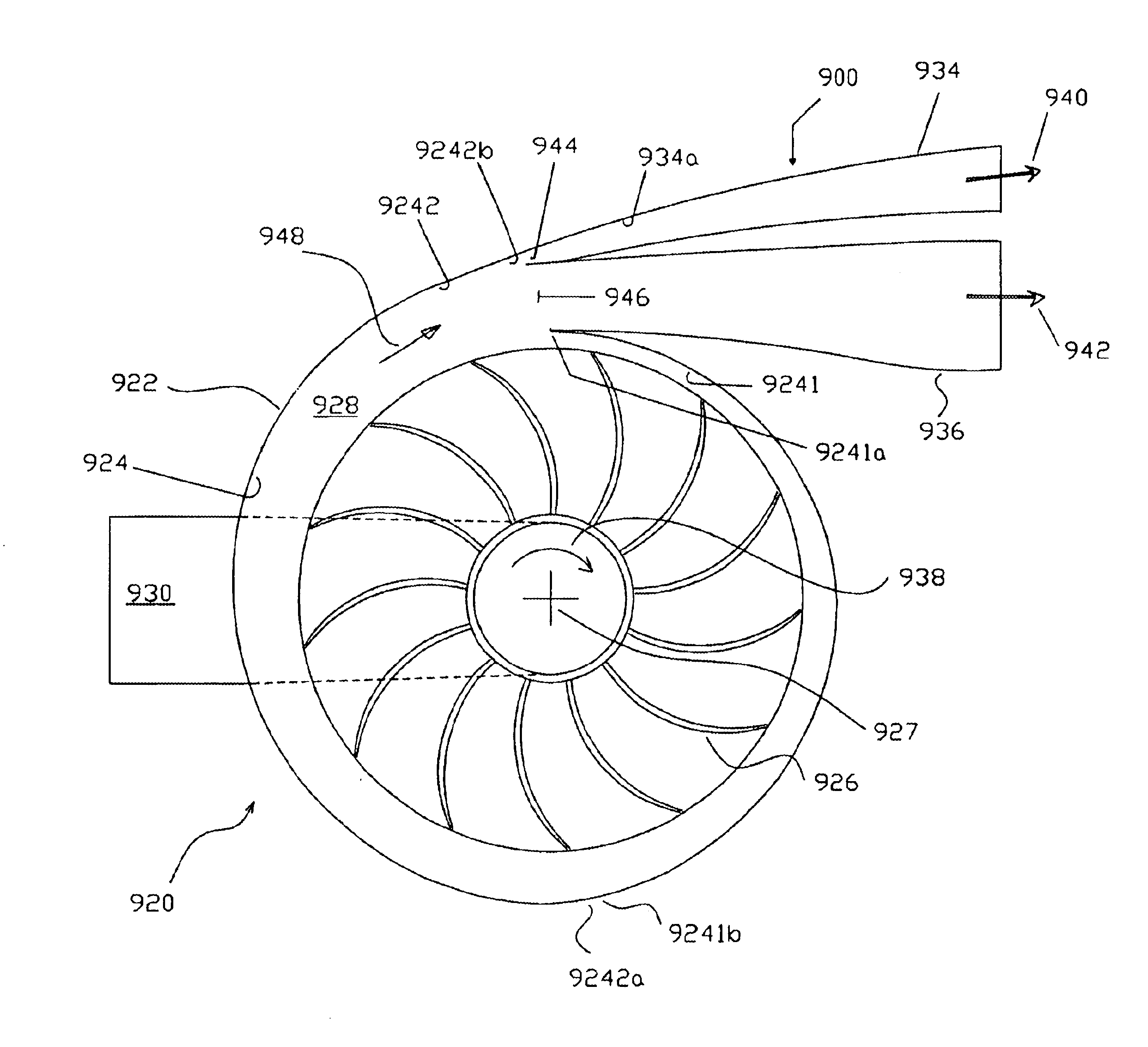
[0070]FIG. 6 shows the meridional view of split stream compressor embodiment 300. The gas flow passes through the inlet flange 301; inlet 302; impeller 303; three diffuser channels 304,305 and 306; three collector scrolls 307, 308 and 309; and three outlets 310, 311 and 312 in outlet flange 313. Within the impeller 303 there are three compartments 314,315 and 316. Compartments 314 and 315 are separated by partition 318, while compartments 315 and 316 are separated by partition 317. Where any portion of partitions 317 and 318 may be deleted, lines 317 and 318 then represent fluid streamlines in the impeller. Partitions 317 and 318 respectively have leading edges 319 and 320 at the inlet and terminate at impeller outer radius 321. The direction of rotation of the impeller 303 is indicated by arrow 322 in FIG. 7.

[0071]The impeller return path is sealed using labyrinth seals 324. The impeller is connected to the shaft 325 using a hub bolt connection 326. The entire volute is connected t...


PUM


Abstract

A gas separation system for separating a feed gas mixture into a first gas component and a second gas component comprises a stator, and a rotor rotatably coupled to the stator. The stator includes a first stator valve face, a second stator valve surface, and a plurality of function compartments opening into the stator valve surfaces. The rotor includes a first rotor valve surface in communication with the first stator valve surface, and a second rotor valve surface in communication with the second stator valve surface. The rotor also includes a plurality of rotor flow paths for receiving gas adsorbent material therein for preferentially adsorbing the first gas component in response to increasing pressure in the rotor flow paths in comparison to the second gas component. Each rotor flow path includes a pair of opposite ends opening into the rotor valve faces for communication with the function compartments. Centrifugal turbomachinery is coupled to a portion of the function compartments, and includes an impeller which has a plurality of impeller flow paths for exposing each rotor flow path to a plurality of discrete pressures as the rotor rotates for separating the first gas component from the second gas component.

Description

[0001]This application is a Continuation-In-Part of application Ser. No. 09 / 464,446, filed Dec. 16, 1999, now U.S. Pat. No. 6,398,853 entitled GAS SEPARATION WITH SPLIT STREAM CENTRIFUGAL TURBOMACHINERY, which claims benefit of U.S. patent application Ser. No. 60 / 112,228, filed Dec. 16, 1998, entitled GAS SEPARATION WITH SPLIT STREAM CENTRIFUGAL TURBOMACHINERY.FIELD OF THE INVENTION[0002]The present invention relates to centrifugal turbomachinery for use with gas separation systems. In particular, the present invention relates to split-stream centrifugal compressors, vacuum pumps and expanders in which the flow exiting or entering the centrifugal turbomachinery comprises multiple flows at different total pressures.BACKGROUND OF THE INVENTION[0003]Gas separation by pressure swing adsorption (PSA) is achieved by coordinated pressure cycling and flow reversals over an adsorbent bed which preferentially adsorbs a more readily adsorbed component relative to a less readily adsorbed compon...

Claims


Application Information

Patent Timeline
Patent Type & Authority Patents(United States)
IPC IPC(8): B01D53/047B01D53/06
CPCB01D53/06B01D53/047B01D53/0431B01D53/0446
Inventor KEEFER, BOWIE G.KAUPERT, KEVIN A.
Owner AIR PROD & CHEM INC
Why Eureka
Try Eureka